METER / GAUGE SYSTEM Tachometer Malfunction
DESCRIPTION
In this circuit, the combination meter assembly receives engine speed signals from the power management control ECU using the CAN communication system. The combination meter assembly displays the engine speed calculated based on the data received from the power management control ECU.
WIRING DIAGRAM
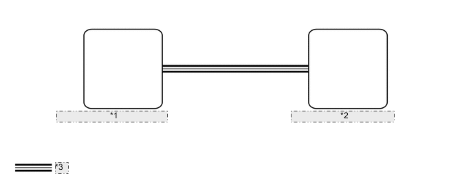
| *1 | Power Management Control ECU |
| *2 | Combination Meter Assembly |
| *3 | CAN Communication Line |
PROCEDURE
-
CHECK CAN COMMUNICATION SYSTEM
-
Check if CAN communication DTCs are output Click here.
Result Result Proceed to CAN communication DTCs are not output. A CAN communication DTCs are output. B
B 
GO TO CAN COMMUNICATION SYSTEM Click here
A 
-
-
PERFORM ACTIVE TEST USING GTS (TACHO METER OPERATION)
-
Connect the GTS to the DLC3.
-
Turn the power switch on (IG).
-
Turn the GTS on.
-
Enter the following menus: Body Electrical / Combination Meter / Active Test.
-
Check the operation by referring to the table below.
Combination Meter Tester Display Test Part Control Range Diagnostic Note Tacho Meter Operation Tachometer OFF, 0, 1000, 2000, 3000, 4000, 5000, 6000, 7000 - OK Tachometer indication is normal.
NG
REPLACE COMBINATION METER ASSEMBLY Click here
OK
-
-
READ VALUE USING GTS (ENGINE RPM)
-
Connect the GTS to the DLC3.
-
Turn the power switch on (IG).
-
Turn the GTS on.
-
Enter the following menus: Body Electrical / Combination Meter / Data List.
-
Check the values by referring to the table below.
Combination Meter Tester Display Measurement Item/Range Normal Condition Diagnostic Note Engine Rpm Engine speed/Min.: 0 rpm, Max.: 12750 rpm Approximately 900 rpm: Idling - OK Engine speed displayed on the GTS is almost the same as the tachometer indication. Tech Tips
-
When the Data List values and tachometer values match, a signal output error of the power management control ECU or an internal malfunction of the combination meter assembly is suspected.
-
When the Data List values and tachometer values do not match, an internal malfunction of the combination meter assembly is suspected.
-
NG
REPLACE COMBINATION METER ASSEMBLY Click here
OK
-
-
CHECK HYBRID CONTROL SYSTEM
-
Check if hybrid control system DTCs are output Click here.
Result Result Proceed to DTCs are not output. A DTCs are output. B
B
GO TO HYBRID CONTROL SYSTEM Click here
A
-
-
READ VALUE USING GTS (ENGINE REVOLUTION, ENGINE RPM)
-
Connect the GTS to the DLC3.
-
Turn the power switch on (IG).
-
Turn the GTS on.
-
Enter the following menus:
-
for Hybrid Control: Powertrain / Hybrid Control / Data List.
-
for Combination Meter: Body Electrical / Combination Meter / Data List.
-
-
Check the values by referring to the table below.
Hybrid Control Tester Display Measurement Item/Range Normal Condition Diagnostic Note Engine Revolution Engine speed/
Min.: 0 rpm, Max.: 16383 rpm
While idling after the engine is warmed up and in inspection mode:
Approximately 900 rpm
While driving at a constant speed:
No significant fluctuation
- Combination Meter Tester Display Measurement Item/Range Normal Condition Diagnostic Note Engine Rpm Engine speed/Min.: 0 rpm, Max.: 12750 rpm Approximately 900 rpm: Idling - Result Result Proceed to The data list values of the ECUs do not match. A The data list values of the ECUs match. B Tech Tips
-
When the Data List values of the ECUs match, an internal malfunction of the power management control ECU is suspected.
-
When the Data List values of the ECUs do not match, a signal output error of the power management control ECU or an internal malfunction of the combination meter assembly is suspected.
-
B
REPLACE POWER MANAGEMENT CONTROL ECU Click here
A
-
-
REPLACE COMBINATION METER ASSEMBLY
-
Replace the combination meter assembly with a new one Click here.
OK The operation of the tachometer returns to normal.
OK
END
NG
REPLACE POWER MANAGEMENT CONTROL ECU Click here
-