Click here
Click here
Click here
-
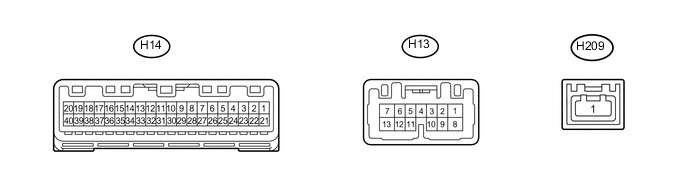
COMBINATION METER ASSEMBLY
-
Measure the voltage and resistance according to the value(s) in the table below.
Terminal No. (Symbol) Wiring Color Terminal Description Condition Specified Condition H13-1 (B) - Body ground R - Body ground Auxiliary battery Power switch off 11 to 14 V H13-2 (HZSW) - Body ground LG - Body ground Hazard warning switch signal (Output) Power switch on (IG), hazard warning signal switch not pressed 11 to 14 V Power switch on (IG), hazard warning signal switch pressed Below 1 V H13-3 (ER) - Body ground P - Body ground RH turn indicator light signal (Input) Power switch on (IG), RH turn switch off 11 to 14 V Power switch on (IG), RH turn switch on Below 1 V H13-4 (EL) - Body ground L - Body ground LH turn indicator light signal (Input) Power switch on (IG), LH turn switch off 11 to 14 V Power switch on (IG), LH turn switch on Below 1 V H13-7 (LR) - Body ground G - Body ground RH turn indicator light signal (Output) Power switch on (IG), RH turn indicator light off 11 to 14 V Power switch on (IG), RH turn indicator light blinking 11 to 14 V ←→ Below 1 V H13-8 (SW) - Body ground G - Body ground LH or RH turn signal switch signal (Input) Power switch on (IG), LH or RH turn signal switch off 11 to 14 V Power switch on (IG), LH or RH turn signal switch on Below 1 V H13-9 (TX-) - Body ground Y - Body ground Local bus communication line - - H13-10 (TX+) - Body ground W - Body ground Local bus communication line - - H13-12 (HAZM) - Body ground V - Body ground Hazard warning switch signal (Input) Power switch on (IG), hazard warning signal switch not pressed Below 1 V Power switch on (IG), hazard warning signal switch pressed 11 to 14 V H13-13 (LL) - Body ground SB - Body ground LH turn indicator light signal (Output) Power switch on (IG), LH turn indicator light off 11 to 14 V Power switch on (IG), LH turn indicator light blinking 11 to 14 V ←→ Below 1 V H14-2 (MSM+) - H14-1 (MSSL) V - W-B Steering pad switch assembly signal Power switch on (IG), enter, back and top switches on steering pad switch assembly not pushed 4.3 to 6 V Power switch on (IG), enter switch on steering pad switch assembly pushed Below 0.6 V Power switch on (IG), back switch on steering pad switch assembly pushed 2.3 to 3.2 V Power switch on (IG), top switch on steering pad switch assembly pushed 1 to 2 V H14-3 (MSTI) - H14-1 (MSSL) B - W-B Steering pad switch assembly signal Power switch on (IG), up, down, right and left switches on steering pad switch assembly not pushed 4.3 to 6 V Power switch on (IG), up switch on steering pad switch assembly pushed 1 to 2 V Power switch on (IG), down switch on steering pad switch assembly pushed 2.3 to 3.2 V Power switch on (IG), right switch on steering pad switch assembly pushed 3.4 to 4.1 V Power switch on (IG), left switch on steering pad switch assembly pushed Below 0.6 V H14-4 (ODO) - H14-26 (SW3) P - B ODO/TRIP switch (Trip switch) signal Power switch on (IG), ODO/TRIP switch not pressed 4 to 6 V Power switch on (IG), ODO/TRIP switch pressed Below 1 V H14-6 (PBKL) - Body ground V*3 or Y*4 - Body ground Front passenger seat belt buckle switch signal Power switch on (IG), front passenger seat occupied, and front passenger seat belt unfastened Below 1 V Power switch on (IG), front passenger seat occupied, and front passenger seat belt fastened 11 to 14 V H14-9 (S) - Body ground B - Body ground Engine oil pressure signal Power switch on (IG), "Oil Pressure Low Stop in a Safe Place See Owner's Manual" not displayed 11 to 14 V Power switch on (IG), "Oil Pressure Low Stop in a Safe Place See Owner's Manual" displayed Below 1 V H14-10 (CHK) - Body ground R - Body ground MIL (Check engine warning light) signal Power switch on (IG), MIL (Check engine warning light) off 11 to 14 V Power switch on (IG), MIL (Check engine warning light) on Below 1 V H14-12 (RRSB)*1 - Body ground LG - Body ground Rear seat belt buckle switch RH signal Power switch on (IG), rear seat belt RH unfastened Below 1 V Power switch on (IG), rear seat belt RH fastened 11 to 14 V H14-13 (RCSB)*1 - Body ground L - Body ground Rear seat belt buckle switch center signal Power switch on (IG), rear seat belt center unfastened Below 1 V Power switch on (IG), rear seat belt center fastened 11 to 14 V H14-14 (RLSB)*1 - Body ground V - Body ground Rear seat belt buckle switch LH signal Power switch on (IG), rear seat belt LH unfastened Below 1 V Power switch on (IG), rear seat belt LH fastened 11 to 14 V H14-16 (WLVL) - Body ground LG - Body ground Washer fluid level signal Power switch on (IG), washer fluid level not low 11 to 14 V Power switch on (IG), washer fluid level low Below 1 V H14-19 (+S) - Body ground W - Body ground Speed signal for other system (Output) Power switch on (IG), wheel being rotated Pulse generation
(See waveform 1)
H14-20 (SI) - Body ground L - Body ground Speed signal for other system (Input) Power switch on (IG), wheel being rotated Pulse generation
(See waveform 1)
H14-21 (IG+) - Body ground GR - Body ground Power switch signal Power switch off Below 1 V Power switch on (IG) 11 to 14 V H14-22 (B) - Body ground G - Body ground Auxiliary battery Power switch off 11 to 14 V H14-25 (TR) - H14-26 (SW3) LG - B Light control rheostat switch (Trip switch) signal Power switch on (IG), light control rheostat up or down switch not pressed 4 to 6 V Power switch on (IG), light control rheostat up or down switch pressed Below 1 V H14-27 (FR) - H14-28 (FE) GR - P Fuel level signal Power switch on (IG), fuel level full Below 1 V Power switch on (IG), fuel level low (fuel level warning light on) 4.5 to 9 V H14-29 (CANH) - Body ground G - Body ground CAN communication line - - H14-30 (CANL) - Body ground W - Body ground CAN communication line - - H14-31 (ES) - Body Ground BR - Body ground Ground Always Below 1 Ω H14-35 (RLBT)*1 - Body Ground R - Body ground Rear seat belt warning light LH output signal Power switch on (IG), rear seat belt warning light LH off 11 to 14 V Power switch on (IG), rear seat belt warning light LH on Below 1 V H14-36 (PBLT)*1 - Body Ground G - Body ground Rear seat belt warning light center output signal Power switch on (IG), rear seat belt warning light center off 11 to 14 V Power switch on (IG), rear seat belt warning light center on Below 1 V H14-37 (RRBT)*1 - Body Ground W - Body ground Rear seat belt warning light RH output signal Power switch on (IG), rear seat belt warning light RH off 11 to 14 V Power switch on (IG), rear seat belt warning light RH on Below 1 V H14-39 (ILL-) - Body ground GR - Body ground Illumination signal Headlight dimmer switch off Below 1 V Headlight dimmer switch in tail or head position Pulse generation H14-40 (EP) - Body Ground W-B - Body ground Ground Always Below 1 Ω H209-1 (GVIF)*2 - Body ground B - Body ground Video signal (Digital) - -
-
*1: w/ Rear Seat Belt Warning
-
*2: w/ Navigation System
-
*3: for LHD
-
*4: for RHD
-
-
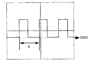
Waveform 1 (Reference):
Item Condition Tool setting 5 V/DIV., 20 ms./DIV. Vehicle condition Power switch on (IG), wheel being rotated Tip:When the system is functioning normally, one wheel revolution generates 4 pulses. As the vehicle speed increases, the width indicated by (A) in the illustration narrows.
-