METER / GAUGE SYSTEM Accessory Meter does not Illuminate
DESCRIPTION
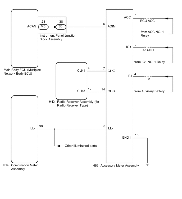
This circuit provides power to the accessory meter assembly.
The accessory meter illumination level can be adjusted by pressing the brightness switch in the radio receiver assembly.
Tech Tips
The radio receiver assembly should be replaced if any of the switches are malfunctioning.
WIRING DIAGRAM
CAUTION / NOTICE / HINT
Note
-
If the main body ECU (multiplex network body ECU) is replaced, refer to Service Bulletin.
-
Inspect the fuses of circuits related to this system before performing the following inspection procedure.
PROCEDURE
-
SYSTEM CHECK
-
Check the operation of the accessory meter assembly.
Result Result Proceed to Accessory meter assembly does not display at all. A Accessory meter assembly does not dim at night. B Accessory meter assembly illumination does not change when the brightness switch is pushed. C
B 
SYSTEM CHECK Click here
C
CHECK HARNESS AND CONNECTOR (RADIO RECEIVER ASSEMBLY - ACCESSORY METER ASSEMBLY) Click here
A 
-
-
CHECK HARNESS AND CONNECTOR (ACCESSORY METER ASSEMBLY CIRCUIT)
-
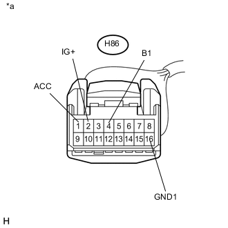
Text in Illustration *a Front view of wire harness connector
(to Accessory Meter Assembly)
Disconnect the H86 accessory meter assembly connector.
-
Measure the voltage according to the value(s) in the table below.
Standard Voltage Tester Connection Condition Specified Condition H86-1 (ACC) - Body ground Power switch on (ACC) 11 to 14 V H86-2 (IG+) - Body ground Power switch on (IG) 11 to 14 V H86-4 (B1) - Body ground Power switch off 11 to 14 V -
Measure the resistance according to the value(s) in the table below.
Standard Resistance Tester Connection Condition Specified Condition H86-16 (GND1) - Body ground Always Below 1 Ω
OK 
REPLACE ACCESSORY METER ASSEMBLY Click here
NG
REPAIR OR REPLACE HARNESS OR CONNECTOR
-
-
SYSTEM CHECK
-
Confirm the symptoms.
Result Result Proceed to All illumination parts do not dim at night. A Only the accessory meter assembly illumination does not dim at night. B
A
REPLACE COMBINATION METER ASSEMBLY Click here
B
-
-
INSPECT MAIN BODY ECU (MULTIPLEX NETWORK BODY ECU)
-
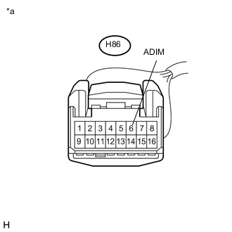
Text in Illustration *a Front view of wire harness connector
(to Accessory Meter Assembly)
Disconnect the H86 accessory meter assembly connector.
-
Measure the voltage according to the value(s) in the table below.
Standard Voltage Tester Connection Condition Specified Condition H86-6 (ADIM) - Body ground Turn the power switch on (IG), turn the headlight dimmer switch assembly to the tail or head position. 4 V or more
NG
CHECK HARNESS AND CONNECTOR (ACCESSORY METER ASSEMBLY - INSTRUMENT PANEL JUNCTION BLOCK ASSEMBLY) Click here
OK
-
-
CHECK HARNESS AND CONNECTOR (ACCESSORY METER ASSEMBLY - COMBINATION METER ASSEMBLY)
-
Disconnect the H14 combination meter assembly connector.
-
Disconnect the H86 accessory meter assembly connector.
-
Measure the resistance according to the value(s) in the table below.
Standard Resistance Tester Connection Condition Specified Condition H86-8 (ILL-) - H14-39 (ILL-) Always Below 1 Ω H86-8 (ILL-) - Body ground Always 10 kΩ or higher
OK
REPLACE ACCESSORY METER ASSEMBLY Click here
NG
REPAIR OR REPLACE HARNESS OR CONNECTOR
-
-
CHECK HARNESS AND CONNECTOR (ACCESSORY METER ASSEMBLY - INSTRUMENT PANEL JUNCTION BLOCK ASSEMBLY)
-
Disconnect the 3B instrument panel junction block assembly connector.
-
Measure the resistance according to the value(s) in the table below.
Standard Resistance Tester Connection Condition Specified Condition H86-6 (ADIM) - 3B-38 (ACAN) Always Below 1 Ω H86-6 (ADIM) - Body ground Always 10 kΩ or higher
NG
REPAIR OR REPLACE HARNESS OR CONNECTOR
OK
-
-
INSPECT INSTRUMENT PANEL JUNCTION BLOCK ASSEMBLY
-
Remove the instrument panel junction block assembly Click here.
-
Remove the main body ECU (multiplex network body ECU) from the instrument panel junction block assembly.
-
Measure the resistance according to the value(s) in the table below.
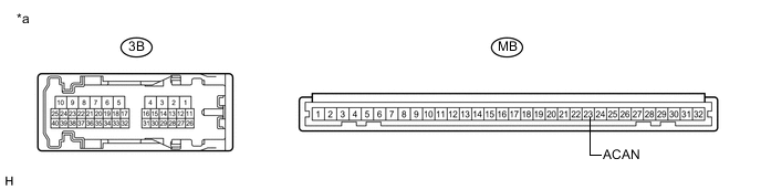
Standard Resistance Tester Connection Condition Specified Condition 3B-38 - MB-23 (ACAN) Always Below 1 Ω Text in Illustration *a Component without harness connected
(Instrument Panel Junction Block Assembly)
- -
OK
REPLACE MAIN BODY ECU (MULTIPLEX NETWORK BODY ECU) Click here
NG
REPLACE INSTRUMENT PANEL JUNCTION BLOCK ASSEMBLY Click here
-
-
CHECK HARNESS AND CONNECTOR (RADIO RECEIVER ASSEMBLY - ACCESSORY METER ASSEMBLY)
-
Disconnect the H42 radio receiver assembly connector.
-
Disconnect the H86 accessory meter assembly connector.
-
Measure the resistance according to the value(s) in the table below.
Standard Resistance Tester Connection Condition Specified Condition H86-7 (CLK2) - H42-4 (CLK1) Always Below 1 Ω H86-7 (CLK2) - Body ground Always 10 kΩ or higher H86-14 (CLK4) - H42-12 (CLK3) Always Below 1 Ω H86-14 (CLK4) - Body ground Always 10 kΩ or higher
NG
REPAIR OR REPLACE HARNESS OR CONNECTOR
OK
-
-
INSPECT RADIO RECEIVER ASSEMBLY
-
Reconnect the H42 radio receiver assembly connector.
-
Measure the resistance according to the value(s) in the table below.
Standard Resistance Tester Connection Condition Specified Condition H86-7 (CLK2) - H86-14 (CLK4) Brightness switch pressed Below 1 Ω Brightness switch not pressed 10 kΩ or higher
OK
REPLACE ACCESSORY METER ASSEMBLY Click here
NG
REPLACE RADIO RECEIVER ASSEMBLY Click here
-