LIGHTING SYSTEM Ambient Light Circuit
DESCRIPTION
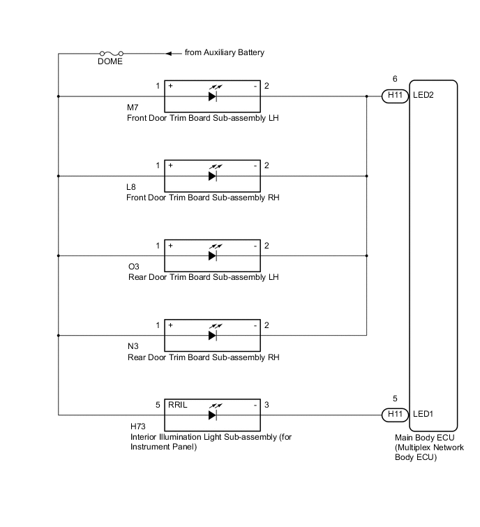
The main body ECU (multiplex network body ECU) controls the ambient lights.
WIRING DIAGRAM
CAUTION / NOTICE / HINT
Note
If the main body ECU (multiplex network body ECU) is replaced, refer to Service Bulletin.
PROCEDURE
-
CHECK SYMPTOMS
-
Check symptoms.
Result Result Proceed to Ambient lights do not illuminate. (for front and rear doors) A Ambient light does not illuminate. (for instrument panel) B
B 
PERFORM ACTIVE TEST USING GTS Click here
A 
-
-
PERFORM ACTIVE TEST USING GTS
-
Connect the GTS to the DLC3.
-
Turn the power switch on (IG).
-
Turn the GTS on.
-
Enter the following menus: Body Electrical / Main Body / Active Test.
-
Check that the ambient lights come on.
Main Body Tester Display Test Part Control Range Diagnostic Note Interior Illumination Light2 Ambient light (for front and rear doors) ON/OFF Power switch is turned off just before performing the Active Test. OK Ambient lights come on.
OK 
PROCEED TO NEXT SUSPECTED AREA SHOWN IN PROBLEM SYMPTOMS TABLE Click here
NG
-
-
CHECK HARNESS AND CONNECTOR (DOME FUSE - DOOR TRIM BOARD SUB-ASSEMBLY)
-
Disconnect the M7 front door trim board sub-assembly LH connector.
-
Disconnect the L8 front door trim board sub-assembly RH connector.
-
Disconnect the O3 rear door trim board sub-assembly LH connector.
-
Disconnect the N3 rear door trim board sub-assembly RH connector.
-
Measure the voltage according to the value(s) in the table below.
Standard Voltage Tester Connection Condition Specified Condition M7-1 (+) - Body ground Power switch off 11 to 14 V L8-1 (+) - Body ground Power switch off 11 to 14 V O3-1 (+) - Body ground Power switch off 11 to 14 V N3-1 (+) - Body ground Power switch off 11 to 14 V
NG
REPAIR OR REPLACE HARNESS OR CONNECTOR
OK
-
-
CHECK HARNESS AND CONNECTOR (DOOR TRIM BOARD SUB-ASSEMBLY - MAIN BODY ECU (MULTIPLEX NETWORK BODY ECU))
-
Disconnect the H11 main body ECU (multiplex network body ECU) connector.
-
Measure the resistance according to the value(s) in the table below.
Standard Resistance Tester Connection Condition Specified Condition M7-2 (-) - H11-6 (LED2) Always Below 1 Ω L8-2 (-) - H11-6 (LED2) Always Below 1 Ω O3-2 (-) - H11-6 (LED2) Always Below 1 Ω N3-2 (-) - H11-6 (LED2) Always Below 1 Ω M7-2 (-) - Body ground Always 10 kΩ or higher
OK
REPLACE MAIN BODY ECU (MULTIPLEX NETWORK BODY ECU) Click here
NG
REPAIR OR REPLACE HARNESS OR CONNECTOR
-
-
PERFORM ACTIVE TEST USING GTS
-
Connect the GTS to the DLC3.
-
Turn the power switch on (IG).
-
Turn the GTS on.
-
Enter the following menus: Body Electrical / Main Body / Active Test.
-
Check that the ambient lights come on.
Main Body Tester Display Test Part Control Range Diagnostic Note Interior Illumination Light1 Ambient light (for instrument panel) ON/OFF Power switch is turned off just before performing the Active Test. OK Ambient light come on.
OK
PROCEED TO NEXT SUSPECTED AREA SHOWN IN PROBLEM SYMPTOMS TABLE Click here
NG
-
-
INSPECT INTERIOR ILLUMINATION LIGHT SUB-ASSEMBLY
-
Remove the interior illumination light sub-assembly Click here.
-
Inspect the interior illumination light sub-assembly Click here.
OK Interior illumination light comes on.
NG
REPLACE INTERIOR ILLUMINATION LIGHT SUB-ASSEMBLY Click here
OK
-
-
CHECK HARNESS AND CONNECTOR (DOME FUSE - INTERIOR ILLUMINATION LIGHT SUB-ASSEMBLY)
-
Disconnect the H73 interior illumination light sub-assembly connector.
-
Measure the voltage according to the value(s) in the table below.
Standard Voltage Tester Connection Condition Specified Condition H73-5 (RRIL) - Body ground Power switch off 11 to 14 V
NG
REPAIR OR REPLACE HARNESS OR CONNECTOR
OK
-
-
CHECK HARNESS AND CONNECTOR (INTERIOR ILLUMINATION LIGHT SUB-ASSEMBLY - MAIN BODY ECU (MULTIPLEX NETWORK BODY ECU))
-
Disconnect the H11 main body ECU (multiplex network body ECU) connector.
-
Measure the resistance according to the value(s) in the table below.
Standard Resistance Tester Connection Condition Specified Condition H73-3 (-) - H11-5 (LED1) Always Below 1 Ω H73-3 (-) - Body ground Always 10 kΩ or higher
OK
REPLACE MAIN BODY ECU (MULTIPLEX NETWORK BODY ECU) Click here
NG
REPAIR OR REPLACE HARNESS OR CONNECTOR
-