LIGHTING SYSTEM Interior Light Auto Cut Circuit
DESCRIPTION
When the battery saving function operates, the main body ECU (multiplex network body ECU) controls the operation of the solid-state relay, that is built into the roof console box assembly, to turn off the interior lights.
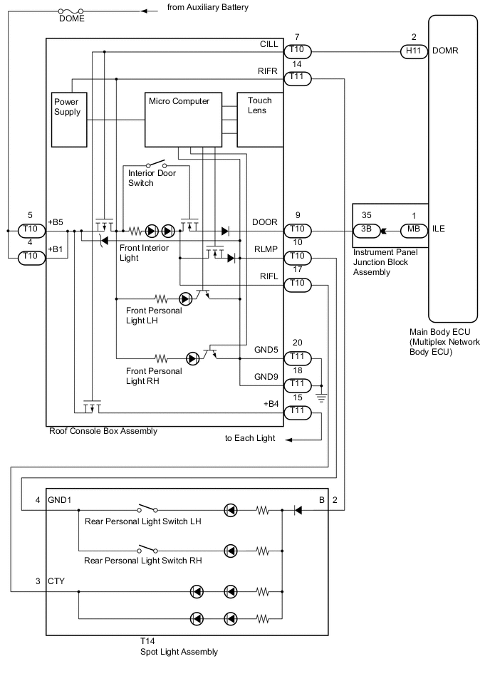
WIRING DIAGRAM
CAUTION / NOTICE / HINT
Note
-
Inspect the fuses for circuits related to this system before performing the following inspection procedure.
-
If the main body ECU (multiplex network body ECU) is replaced, refer to Service Bulletin.
PROCEDURE
-
PERFORM ACTIVE TEST USING GTS
-
Connect the GTS to the DLC3.
-
Turn the power switch on (IG).
-
Turn the GTS on.
-
Enter the following menus: Body Electrical / Main Body / Active Test.
-
Check that the relay operates.
Main Body Tester Display Test Part Control Range Diagnostic Note Relay for Interior Light Auto Cut Function Solid-state relay (built into roof console box assembly) ON/OFF - OK Light auto cut relay operates.
OK 
PROCEED TO NEXT SUSPECTED AREA SHOWN IN PROBLEM SYMPTOMS TABLE Click here
NG 
-
-
INSPECT ROOF CONSOLE BOX ASSEMBLY
-
Remove the roof console box assembly Click here.
-
Inspect the roof console box assembly Click here.
OK Roof console box assembly is normal.
NG
REPLACE ROOF CONSOLE BOX ASSEMBLY Click here
OK
-
-
CHECK HARNESS AND CONNECTOR (ROOF CONSOLE BOX ASSEMBLY - MAIN BODY ECU (MULTIPLEX NETWORK BODY ECU))
-
Disconnect the H11 main body ECU (multiplex network body ECU) connector.
-
Measure the resistance according to the value(s) in the table below.
Standard Resistance Tester Connection Condition Specified Condition T10-7 (CILL) - H11-2 (DOMR) Always Below 1 Ω T10-7 (CILL) - Body ground Always 10 kΩ or higher
OK
REPLACE MAIN BODY ECU (MULTIPLEX NETWORK BODY ECU) Click here
NG
REPAIR OR REPLACE HARNESS OR CONNECTOR
-