| DTC Code | DTC Name |
|---|---|
| IG Signal Circuit |
DESCRIPTION
This circuit detects the power switch on (IG) or off condition, and sends it to the main body ECU (multiplex network body ECU).
CAUTION / NOTICE / HINT
-
Inspect the fuses for circuits related to this system before performing the following inspection procedure.
-
If the main body ECU (multiplex network body ECU) is replaced, refer to Service Bulletin.
PROCEDURE
- Click here
CHECK DTC (SMART ENTRY AND START SYSTEM (for Start Function))
-
Check for DTCs (Click here)
Table 1. Result Result Proceed to DTC is not output A DTC is output B
- AClick here
- B
GO TO SMART ENTRY AND START SYSTEM (for Start Function) (Click here)
-
- Click here
READ VALUE USING GTS
-
Connect the GTS to the DLC3.
-
Turn the power switch on (IG).
-
Turn the GTS on.
-
Enter the following menus: Body Electrical / Main Body / Data List.
-
Read the display on the GTS.
Table 2. Main Body Tester Display Measurement Item/Range Normal Condition Diagnostic Note IG SW Power switch on (IG) signal/ON or OFF ON: Power switch on (IG)
OFF: Power switch off
- OK Normal conditions listed above are displayed.
- OK
PROCEED TO NEXT SUSPECTED AREA SHOWN IN PROBLEM SYMPTOMS TABLE (Click here)
- NGClick here
-
- Click here
CHECK HARNESS AND CONNECTOR (ALT FUSE - INSTRUMENT PANEL JUNCTION BLOCK ASSEMBLY)
-
Disconnect the 3E instrument panel junction block assembly connectors.
-
Measure the voltage according to the value(s) in the table below.
Standard Voltage Tester Connection Condition Specified Condition 3E-1 - Body ground Power switch off 11 to 14 V
- OKClick here
- NG
REPAIR OR REPLACE HARNESS OR CONNECTOR
-
- Click here
INSPECT INSTRUMENT PANEL JUNCTION BLOCK ASSEMBLY
-
Remove the instrument panel junction block assembly (Click here).
-
Remove the main body ECU (multiplex network body ECU) from the instrument panel junction block assembly.
-
Measure the resistance according to the value(s) in the table below.
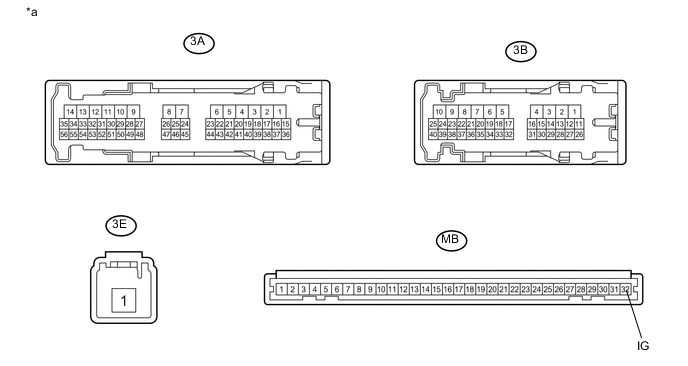
Table 3. Text in Illustration *a Component without harness connected
(Instrument Panel Junction Block Assembly)
- - Standard Resistance Tester Connection Condition Specified Condition 3E-1 - MB-32 (IG) Always 10 kΩ or higher 3E-1 - MB-32 (IG) Auxiliary battery positive (+) → 3A-27
Auxiliary battery negative (-) → 3B-7
Below 1 Ω
- OK
REPLACE MAIN BODY ECU (MULTIPLEX NETWORK BODY ECU) (Click here)
- NG
REPLACE INSTRUMENT PANEL JUNCTION BLOCK ASSEMBLY (Click here)
-