-
After turning the power switch off, waiting time may be required before disconnecting the cable from the negative (-) auxiliary battery terminal. Therefore, make sure to read the disconnecting the cable from the negative (-) auxiliary battery terminal notices before proceeding with work (Click here).
-
Turn the power switch off before measuring the resistances between CAN main bus lines and between CAN branch lines.
-
Turn the power switch off before inspecting CAN bus lines for a ground short.
-
Before measuring the resistance of the CAN bus, turn the power switch off and leave the vehicle for 1 minute or more without operating the key, switches or opening or closing the doors. After that, disconnect the cable from the negative (-) auxiliary battery terminal and leave the vehicle for 1 minute or more before measuring the resistance.
-
This section describes the standard values for all CAN related components.
-
Operating the power switch, any other switches or a door triggers related ECU and sensor communication on the CAN. This communication will cause the resistance value to change.
-
Even after DTCs are cleared, if a DTC is stored again after driving the vehicle for a while, the malfunction may be occurring due to vibration of the vehicle. In such a case, wiggling the ECUs or wire harness while performing the inspection below may help determine the cause of the malfunction.
Click here
-
CAN JUNCTION CONNECTOR LH1 (for LHD)
-
Check the CAN junction connector LH1.
Tip:Connectors that connect to the CAN junction connector can be distinguished by the color of their CAN bus lines. When the connectors have been disconnected from the CAN junction connector, reconnecting the connectors to non-original positions on the CAN junction connector does not affect system performance. However, it is preferred to reconnect the connectors to their original positions to avoid negative effects on the wiring such as tension on the wiring harnesses, and to make future maintenance easier.
-
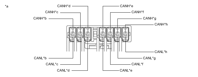
Connection diagram
Table 1. Text in Illustration *a Component with harness connected
(CAN Junction Connector LH1)
*b to Brake Booster with Master Cylinder Assembly (Skid Control ECU)
(for V Bus)
*c to Steering Sensor
(for V Bus)
*d to Main Body ECU (Multiplex Network Body ECU)
(for V Bus)
*e to DLC3
(for V Bus)
*f to Combination Meter Assembly
(for V Bus)
*g to CAN Junction Connector RH1
(for V Bus)
*h to Power Management Control ECU
(for V Bus)
-
Check the connection diagram of the components which are connected to the CAN junction connector LH1.
Terminal No. (Symbol) Wiring Color Connected to H116-1 (CANH) R CAN junction connector RH1
(for V bus)
H116-2 (CANL) W H117-1 (CANH) G Combination meter assembly
(for V bus)
H117-2 (CANL) W H118-1 (CANH) V Main body ECU (multiplex network body ECU)
(for V bus)
H118-2 (CANL) W H119-1 (CANH) L DLC3
(for V bus)
H119-2 (CANL) W H120-1 (CANH) P Steering sensor
(for V bus)
H120-2 (CANL) W H130-1 (CANH) B Power management control ECU
(for V bus)
H130-2 (CANL) W H131-1 (CANH) BE Brake booster with master cylinder assembly (Skid control ECU)
(for V bus)
H131-2 (CANL) W
-
-
-
CAN JUNCTION CONNECTOR RH1 (for LHD)
-
Check the CAN junction connector RH1.
Tip:Connectors that connect to the CAN junction connector can be distinguished by the color of their CAN bus lines. When the connectors have been disconnected from the CAN junction connector, reconnecting the connectors to non-original positions on the CAN junction connector does not affect system performance. However, it is preferred to reconnect the connectors to their original positions to avoid negative effects on the wiring such as tension on the wiring harnesses, and to make future maintenance easier.
-
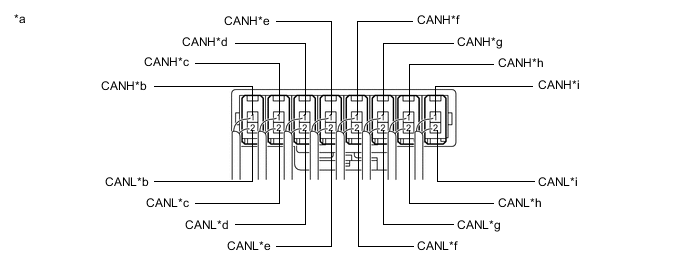
Connection diagram
Table 2. Text in Illustration *a Component with harness connected
(CAN Junction Connector RH1)
*b to Multi-media Module Receiver Assembly*
(for V Bus)
*c to Clearance Warning ECU Assembly
(for V Bus)
*d to Certification ECU (Smart Key ECU Assembly)
(for V Bus)
*e to Airbag Sensor Assembly
(for V Bus)
*f to ECM
(for V Bus)
*g to Air Conditioning Amplifier Assembly
(for V Bus)
*h to CAN Junction Connector LH1
(for V Bus)
*i to Power Steering ECU with Motor Assembly
(for V Bus)
- - *: w/ Navigation system
-
Check the connection diagram of the components which are connected to the CAN junction connector RH1.
Terminal No. (Symbol) Wiring Color Connected to H121-1 (CANH) B Power steering ECU with motor assembly
(for V bus)
H121-2 (CANL) W H122-1 (CANH) R CAN junction connector LH1
(for V bus)
H122-2 (CANL) W H123-1 (CANH) G Air conditioning amplifier assembly
(for V bus)
H123-2 (CANL) W H124-1 (CANH) Y Airbag sensor assembly
(for V bus)
H124-2 (CANL) W H125-1 (CANH) L ECM
(for V bus)
H125-2 (CANL) W H127-1 (CANH) V Certification ECU (smart key ECU assembly)
(for V bus)
H127-2 (CANL) W H128-1 (CANH) BE Multi-media module receiver assembly*
(for V bus)
H128-2 (CANL) W H132-1 (CANH) P Clearance warning ECU assembly
(for V bus)
H132-2 (CANL) W *: w/ Navigation system
-
-
-
CAN JUNCTION CONNECTOR LH2 (for LHD)
-
Check the CAN junction connector LH2.
Tip:Connectors that connect to the CAN junction connector can be distinguished by the color of their CAN bus lines. When the connectors have been disconnected from the CAN junction connector, reconnecting the connectors to non-original positions on the CAN junction connector does not affect system performance. However, it is preferred to reconnect the connectors to their original positions to avoid negative effects on the wiring such as tension on the wiring harnesses, and to make future maintenance easier.
-
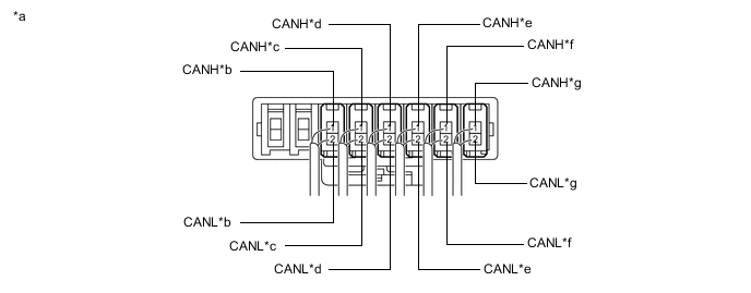
Connection diagram
Table 3. Text in Illustration *a Component with harness connected
(CAN Junction Connector LH2)
*b to Luggage Closer Motor Assembly*1
(for Sub Bus 1)
*c to Main Body ECU (Multiplex Network Body ECU)
(for Sub Bus 1)
*d Multiplex Tilt and Telescopic ECU*2
(for Sub Bus 1)
*e to Outer Mirror Control ECU Assembly LH*2
(for Sub Bus 1)
*f to Front Power Seat Switch LH*2
(for Sub Bus 1)
*g to CAN Junction Connector RH2
(for Sub Bus 1)
- -
-
*1: w/ Power trunk lid system
-
*2: w/ Seat position memory system (for driver side)
-
-
Check the connection diagram of the components which are connected to the junction connector LH2.
Terminal No. (Symbol) Wiring Color Connected to H135-1 (CANH) V Luggage closer motor assembly*1
(for Sub bus 1)
H135-2 (CANL) GR H136-1 (CANH) Y Main body ECU (multiplex network body ECU)
(for Sub bus 1)
H136-2 (CANL) GR H137-1 (CANH) L Multiplex tilt and telescopic ECU*2
(for Sub bus 1)
H137-2 (CANL) GR H138-1 (CANH) G Outer mirror control ECU assembly LH*2
(for Sub bus 1)
H138-2 (CANL) GR H140-1 (CANH) R Front power seat switch LH*2
(for Sub bus 1)
H140-2 (CANL) GR H142-1 (CANH) B CAN junction connector RH2
(for Sub bus 1)
H142-2 (CANL) GR
-
*1: w/ Power trunk lid system
-
*2: w/ Seat position memory system (for driver side)
-
-
-
-
CAN JUNCTION CONNECTOR RH2 (for LHD)
-
Check the CAN junction connector RH2.
Tip:Connectors that connect to the CAN junction connector can be distinguished by the color of their CAN bus lines. When the connectors have been disconnected from the CAN junction connector, reconnecting the connectors to non-original positions on the CAN junction connector does not affect system performance. However, it is preferred to reconnect the connectors to their original positions to avoid negative effects on the wiring such as tension on the wiring harnesses, and to make future maintenance easier.
-
Connection diagram
Table 4. Text in Illustration *a Component with harness connected
(CAN Junction Connector RH2)
*b to CAN No. 2 Junction Connector
(for Sub Bus 1)
*c to Front Power Seat Switch RH*2
(for Sub Bus 1)
*d to Outer Mirror Control ECU Assembly RH*1
(for Sub Bus 1)
*e to CAN Junction Connector LH2
(for Sub Bus 1)
- -
-
*1: w/ Seat position memory system (for driver side)
-
*2: w/ Seat position memory system (for front passenger side)
-
-
Check the connection diagram of the components which are connected to the CAN junction connector RH2.
Terminal No. (Symbol) Wiring Color Connected to H139-1 (CANH) R Outer mirror control ECU assembly RH*1
(for Sub bus 1)
H139-2 (CANL) GR H141-1 (CANH) G Front power seat switch RH*2
(for Sub bus 1)
H141-2 (CANL) GR H143-1 (CANH) B CAN junction connector LH2
(for Sub bus 1)
H143-2 (CANL) GR H144-1 (CANH) L CAN No. 2 junction connector
(for Sub bus 1)
H144-2 (CANL) GR
-
*1: w/ Seat position memory system (for driver side)
-
*2: w/ Seat position memory system (for front passenger side)
-
-
-
-
CAN JUNCTION CONNECTOR RH3 (for LHD w/ Dynamic Radar Cruise Control System)
-
Check the CAN junction connector RH3.
Tip:Connectors that connect to the CAN junction connector can be distinguished by the color of their CAN bus lines. When the connectors have been disconnected from the CAN junction connector, reconnecting the connectors to non-original positions on the CAN junction connector does not affect system performance. However, it is preferred to reconnect the connectors to their original positions to avoid negative effects on the wiring such as tension on the wiring harnesses, and to make future maintenance easier.
-
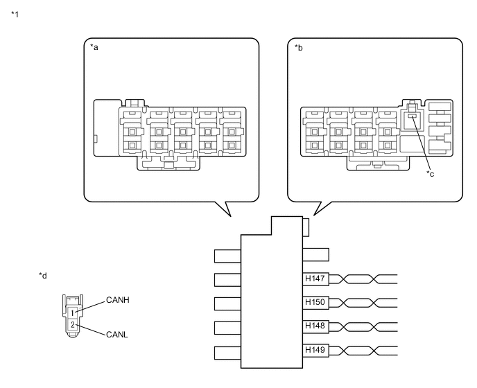
Connection diagram
Table 5. Text in Illustration *1 CAN Junction Connector RH3 - - *a Junction Connector A Side *b Junction Connector B Side *c Ground Terminal *d Front view of wire harness connector
(to CAN Junction Connector RH3)
-
-
Check the connection diagram of the components which are connected to the CAN junction connector RH3.
Table 6. Junction Connector B Side Terminal No. (Symbol) Wiring Color Connected to H147-1 (CANH) B CAN No. 4 junction connector
(for Sub bus 11)
H147-2 (CANL) LG H148-1 (CANH) G Seat belt control ECU
(for Sub bus 11)
H148-2 (CANL) LG H149-1 (CANH) L Power management control ECU
(for Sub bus 11)
H149-2 (CANL) LG H150-1 (CANH) R Driving support ECU assembly
(for Sub bus 11)
H150-2 (CANL) LG
-
-
CAN JUNCTION CONNECTOR RH3 (for LHD w/o Dynamic Radar Cruise Control System)
-
Check the CAN junction connector RH3.
Tip:Connectors that connect to the CAN junction connector can be distinguished by the color of their CAN bus lines. When the connectors have been disconnected from the CAN junction connector, reconnecting the connectors to non-original positions on the CAN junction connector does not affect system performance. However, it is preferred to reconnect the connectors to their original positions to avoid negative effects on the wiring such as tension on the wiring harnesses, and to make future maintenance easier.
-
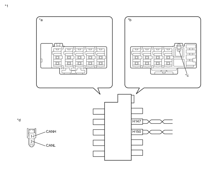
Connection diagram
Table 7. Text in Illustration *1 CAN Junction Connector RH3 - - *a Junction Connector A Side *b Junction Connector B Side *c Ground Terminal *d Front view of wire harness connector
(to CAN Junction Connector RH3)
-
-
Check the connection diagram of the components which are connected to the CAN junction connector RH3.
Table 8. Junction Connector B Side Terminal No. (Symbol) Wiring Color Connected to H147-1 (CANH) B CAN No. 4 junction connector
(for Sub bus 11)
H147-2 (CANL) LG H150-1 (CANH) R CAN No. 3 junction connector
(for Sub bus 11)
H150-2 (CANL) LG
-
-
CAN JUNCTION CONNECTOR LH1 (for RHD)
-
Check the CAN junction connector LH1.
Tip:Connectors that connect to the CAN junction connector can be distinguished by the color of their CAN bus lines. When the connectors have been disconnected from the CAN junction connector, reconnecting the connectors to non-original positions on the CAN junction connector does not affect system performance. However, it is preferred to reconnect the connectors to their original positions to avoid negative effects on the wiring such as tension on the wiring harnesses, and to make future maintenance easier.
-
Connection diagram
Table 9. Text in Illustration *a Component with harness connected
(CAN Junction Connector LH1)
*b to Multi-media Module Receiver Assembly*
(for V Bus)
*c to Power Steering ECU with Motor Assembly
(for V Bus)
*d to Main Body ECU (Multiplex Network Body ECU)
(for V Bus)
*e to Airbag Sensor Assembly
(for V Bus)
*f to ECM
(for V Bus)
*g to Air Conditioning Amplifier Assembly
(for V Bus)
*h to CAN Junction Connector RH1
(for V Bus)
*i to Power Management Control ECU
(for V Bus)
- -
-
*: w/ Navigation system
-
-
Check the connection diagram of the components which are connected to the CAN junction connector LH1.
Terminal No. (Symbol) Wiring Color Connected to H128-1 (CANH) BE Multi-media module receiver assembly*
(for V bus)
H128-2 (CANL) W H121-1 (CANH) P Power steering ECU with motor assembly
(for V bus)
H121-2 (CANL) W H118-1 (CANH) V Main body ECU (multiplex network body ECU)
(for V bus)
H118-2 (CANL) W H124-1 (CANH) Y Airbag sensor assembly
(for V bus)
H124-2 (CANL) W H125-1 (CANH) L ECM
(for V bus)
H125-2 (CANL) W H123-1 (CANH) G Air conditioning amplifier assembly
(for V bus)
H123-2 (CANL) W H116-1 (CANH) R CAN junction connector RH1
(for V bus)
H116-2 (CANL) W H130-1 (CANH) B Power management control ECU
(for V bus)
H130-2 (CANL) W
-
*: w/ Navigation system
-
-
-
-
CAN JUNCTION CONNECTOR RH1 (for RHD)
-
Check the CAN junction connector RH1.
Tip:Connectors that connect to the CAN junction connector can be distinguished by the color of their CAN bus lines. When the connectors have been disconnected from the CAN junction connector, reconnecting the connectors to non-original positions on the CAN junction connector does not affect system performance. However, it is preferred to reconnect the connectors to their original positions to avoid negative effects on the wiring such as tension on the wiring harnesses, and to make future maintenance easier.
-
Connection diagram
Table 10. Text in Illustration *a Component with harness connected
(CAN Junction Connector RH1)
*b to Steering Sensor
(for V Bus)
*c to Clearance Warning ECU Assembly
(for V Bus)
*d to Certification ECU (Smart Key ECU Assembly)
(for V Bus)
*e to DLC3
(for V Bus)
*f to Combination Meter Assembly
(for V Bus)
*g to CAN Junction Connector LH1
(for V Bus)
*h to Brake Booster with Master Cylinder Assembly (Skid Control ECU)
(for V Bus)
-
Check the connection diagram of the components which are connected to the CAN junction connector RH1.
Terminal No. (Symbol) Wiring Color Connected to H120-1 (CANH) BE Steering sensor
(for V bus)
H120-2 (CANL) W H132-1 (CANH) P Clearance warning ECU assembly
(for V bus)
H132-2 (CANL) W H127-1 (CANH) V Certification ECU (smart key ECU assembly)
(for V bus)
H127-2 (CANL) W H119-1 (CANH) L DLC3
(for V bus)
H119-2 (CANL) W H117-1 (CANH) G Combination meter assembly
(for V bus)
H117-2 (CANL) W H122-1 (CANH) R CAN junction connector LH1
(for V bus)
H122-2 (CANL) W H131-1 (CANH) B Brake booster with master cylinder assembly (skid control ECU)
(for V bus)
H131-2 (CANL) W
-
-
-
CAN JUNCTION CONNECTOR LH2 (for RHD)
-
Check the CAN junction connector LH2.
Tip:Connectors that connect to the CAN junction connector can be distinguished by the color of their CAN bus lines. When the connectors have been disconnected from the CAN junction connector, reconnecting the connectors to non-original positions on the CAN junction connector does not affect system performance. However, it is preferred to reconnect the connectors to their original positions to avoid negative effects on the wiring such as tension on the wiring harnesses, and to make future maintenance easier.
-
Connection diagram
Table 11. Text in Illustration *a Component with harness connected
(CAN Junction Connector LH2)
*b to Main Body ECU (Multiplex Network Body ECU)
(for Sub Bus 1)
*c to Outer Mirror Control ECU Assembly LH
(for Sub Bus 1)
*d to Front Power Seat Switch LH*
(for Sub Bus 1)
*e to CAN Junction Connector RH2
(for Sub Bus 1)
- - *: w/ Seat position memory system (for front passenger side)
-
Check the connection diagram of the components which are connected to the junction connector LH2.
Terminal No. (Symbol) Wiring Color Connected to H136-1 (CANH) L Main body ECU (multiplex network body ECU)
(for Sub bus 1)
H136-2 (CANL) GR H138-1 (CANH) G Outer mirror control ECU assembly LH
(for Sub bus 1)
H138-2 (CANL) GR H140-1 (CANH) R Front power seat switch LH*
(for Sub bus 1)
H140-2 (CANL) GR H142-1 (CANH) B CAN junction connector RH2
(for Sub bus 1)
H142-2 (CANL) GR *: w/ Seat position memory system (for front passenger side)
-
-
-
CAN JUNCTION CONNECTOR RH2 (for RHD)
-
Check the CAN junction connector RH2.
Tip:Connectors that connect to the CAN junction connector can be distinguished by the color of their CAN bus lines. When the connectors have been disconnected from the CAN junction connector, reconnecting the connectors to non-original positions on the CAN junction connector does not affect system performance. However, it is preferred to reconnect the connectors to their original positions to avoid negative effects on the wiring such as tension on the wiring harnesses, and to make future maintenance easier.
-
Connection diagram
Table 12. Text in Illustration *a Component with harness connected
(CAN Junction Connector RH2)
*b to CAN No. 2 Junction Connector
(for Sub Bus 1)
*c to Luggage Closer Motor Assembly*1
(for Sub Bus 1)
*d Multiplex Tilt and Telescopic ECU*2
(for Sub Bus 1)
*e to Front Power Seat Switch RH
(for Sub Bus 1)
*f to Outer Mirror Control ECU Assembly RH
(for Sub Bus 1)
*g to CAN Junction Connector LH2
(for Sub Bus 1)
- -
-
*1: w/ Power trunk lid system
-
*2: w/ Power tilt and power telescopic steering column system
-
-
Check the connection diagram of the components which are connected to the CAN junction connector RH2.
Terminal No. (Symbol) Wiring Color Connected to H143-1 (CANH) B CAN junction connector LH2
(for Sub bus 1)
H143-2 (CANL) GR H135-1 (CANH) Y Luggage closer motor assembly*1
(for Sub bus 1)
H135-2 (CANL) GR H137-1 (CANH) L Multiplex tilt and telescopic ECU*2
(for Sub bus 1)
H137-2 (CANL) GR H141-1 (CANH) G Front power seat switch RH
(for Sub bus 1)
H141-2 (CANL) GR H139-1 (CANH) R Outer mirror control ECU assembly RH
(for Sub bus 1)
H139-2 (CANL) GR H144-1 (CANH) V CAN No. 2 junction connector
(for Sub bus 1)
H144-2 (CANL) GR
-
*1: w/ Power trunk lid system
-
*2: w/ Power tilt and power telescopic steering column system
-
-
-
-
CAN JUNCTION CONNECTOR RH3 (for RHD)
-
Check the CAN junction connector RH3.
Tip:Connectors that connect to the CAN junction connector can be distinguished by the color of their CAN bus lines. When the connectors have been disconnected from the CAN junction connector, reconnecting the connectors to non-original positions on the CAN junction connector does not affect system performance. However, it is preferred to reconnect the connectors to their original positions to avoid negative effects on the wiring such as tension on the wiring harnesses, and to make future maintenance easier.
-
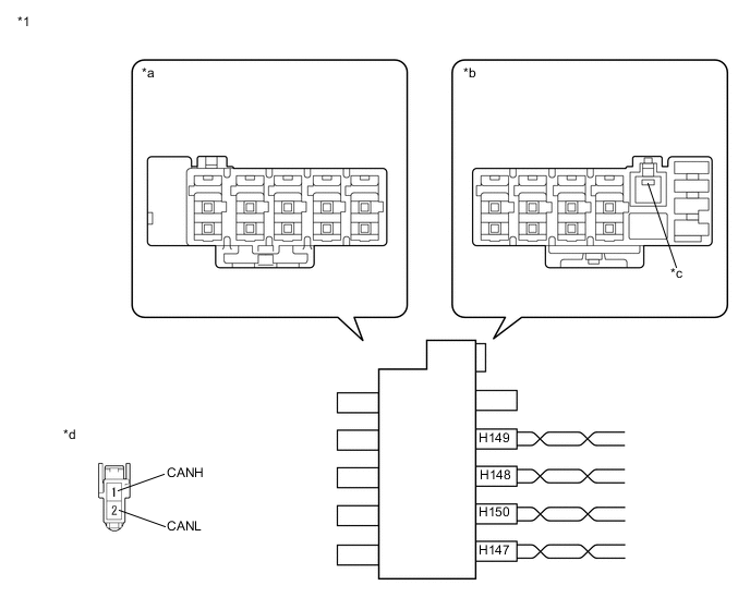
Connection diagram
Table 13. Text in Illustration *1 CAN Junction Connector RH3 - - *a Junction Connector A Side *b Junction Connector B Side *c Ground Terminal *d Front view of wire harness connector
(to CAN Junction Connector RH3)
-
-
Check the connection diagram of the components which are connected to the CAN junction connector RH3.
Table 14. Junction Connector B Side Terminal No. (Symbol) Wiring Color Connected to H149-1 (CANH) L Power management control ECU
(for Sub bus 11)
H149-2 (CANL) LG H148-1 (CANH) G Seat belt control ECU*
(for Sub bus 11)
H148-2 (CANL) LG H150-1 (CANH) R Driving support ECU assembly*
(for Sub bus 11)
H150-2 (CANL) LG H147-1 (CANH) B CAN No. 4 junction connector
(for Sub bus 11)
H147-2 (CANL) LG
-
*: w/ Dynamic radar cruise control system
-
-
-
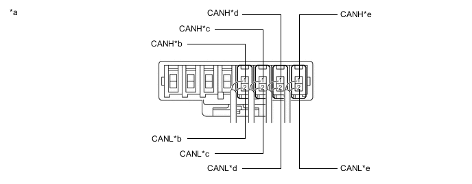
CAN NO. 1 JUNCTION CONNECTOR (for LHD)
-
Check the CAN No. 1 junction connector.
-
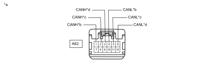
Connection diagram
Table 15. Text in Illustration *a Front view of wire harness connector
(to CAN No. 1 Junction Connector)
*b to Brake Booster with Master Cylinder Assembly (Skid Control ECU)
(for Sub Bus 15)
*c to ECM
(for Sub Bus 15)
*d to Power Management Control ECU
(for Sub Bus 15)
-
Check the connection diagram of the components which are connected to the CAN No. 1 junction connector.
Terminal No. (Symbol) Wiring Color Connected to A62-1 (CANH) B Brake booster with master cylinder assembly (skid control ECU)
(for Sub bus 15)
A62-4 (CANL) W A62-2 (CANH) B ECM
(for Sub bus 15)
A62-5 (CANL) W A62-3 (CANH) B Power management control ECU
(for Sub bus 15)
A62-6 (CANL) W
-
-
-
CAN NO. 2 JUNCTION CONNECTOR
-
Check the CAN No. 2 junction connector.
-
Connection diagram
Table 16. Text in Illustration *a Rear view of wire harness connector
(to CAN No. 2 Junction Connector)
*b to CAN Junction Connector RH2
(for Sub Bus 1)
-
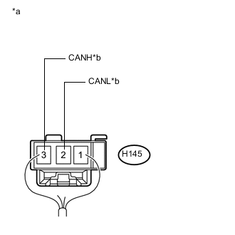
Check the connection diagram of the components which are connected to the CAN No. 2 junction connector.
Terminal No. (Symbol) Wiring Color Connected to H145-3 (CANH) L*1
V*2
CAN junction connector RH2
(for Sub bus 1)
H145-2 (CANL) GR
-
*1: for LHD
-
*2: for RHD
-
-
-
-
CAN NO. 3 JUNCTION CONNECTOR (for LHD w/ Dynamic Radar Cruise Control System)
-
Check the CAN No. 3 junction connector.
-
Connection diagram
Table 17. Text in Illustration *a Front view of wire harness connector
(to CAN No. 3 Junction Connector)
*b to Driving Support ECU Assembly
(for Sub Bus 13)
*c to Millimeter Wave Radar Sensor Assembly
(for Sub Bus 13)
*d to Lane Departure Warning Camera*
(for Sub Bus 13)
-
*: w/ Lane departure alert system
-
-
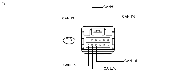
Check the connection diagram of the components which are connected to the CAN No. 3 junction connector.
Terminal No. (Symbol) Wiring Color Connected to T13-1 (CANH) B Driving support ECU assembly
(for Sub bus 13)
T13-7 (CANL) W T13-2 (CANH) R Millimeter wave radar sensor assembly
(for Sub bus 13)
T13-8 (CANL) LG T13-3 (CANH) B Lane departure warning camera*
(for Sub bus 13)
T13-9 (CANL) W
-
*: w/ Lane departure alert system
-
-
-
-
CAN NO. 3 JUNCTION CONNECTOR (for LHD w/o Dynamic Radar Cruise Control System)
-
Check the CAN No. 3 junction connector.
-
Connection diagram
Table 18. Text in Illustration *a Front view of wire harness connector
(to CAN No. 3 Junction Connector)
*b to Power Management Control ECU
(for Sub Bus 11)
*c to CAN Junction Connector RH3
(for Sub Bus 11)
*d to Lane Departure Warning Camera*
(for Sub Bus 11)
-
*: w/ Lane departure alert system
-
-
Check the connection diagram of the components which are connected to the CAN No. 3 junction connector.
Terminal No. (Symbol) Wiring Color Connected to T13-1 (CANH) B Power management control ECU
(for Sub bus 11)
T13-7 (CANL) W T13-2 (CANH) R CAN junction connector RH3
(for Sub bus 11)
T13-8 (CANL) LG T13-3 (CANH) B Lane departure warning camera*
(for Sub bus 11)
T13-9 (CANL) W
-
*: w/ Lane departure alert system
-
-
-
-
CAN NO. 4 JUNCTION CONNECTOR
-
Check the CAN No. 4 junction connector.
-
Connection diagram
Table 19. Text in Illustration *a Front view of wire harness connector
(to CAN No. 4 Junction Connector)
*b to CAN Junction Connector RH3
(for Sub Bus 11)
*c to Blind Spot Monitor Sensor LH*
(for Sub Bus 11)
*d to CAN No. 5 Junction Connector
(for Sub Bus 11)
*: w/ Blind spot monitor system
-
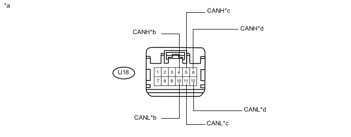
Check the connection diagram of the components which are connected to the CAN No. 4 junction connector.
Terminal No. (Symbol) Wiring Color Connected to U18-4 (CANH) B CAN junction connector RH3
(for Sub bus 11)
U18-10 (CANL) W U18-5 (CANH) B Blind spot monitor sensor LH*
(for Sub bus 11)
U18-11 (CANL) R U18-6 (CANH) B CAN No. 5 junction connector
(for Sub bus 11)
U18-12 (CANL) W *: w/ Blind spot monitor system
-
-
-
CAN NO. 5 JUNCTION CONNECTOR
-
Check the CAN No. 5 junction connector.
-
Connection diagram
Table 20. Text in Illustration *a Rear view of wire harness connector
(to CAN No. 5 Junction Connector)
*b to CAN No. 4 Junction Connector
(for Sub Bus 11)
-
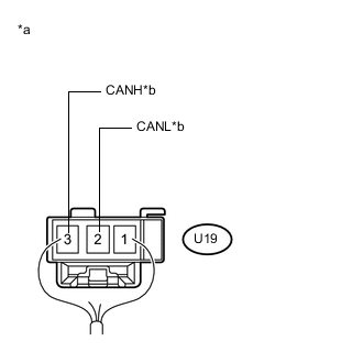
Check the connection diagram of the components which are connected to the CAN No. 5 junction connector.
Terminal No. (Symbol) Wiring Color Connected to U19-3 (CANH) B CAN No. 4 junction connector
(for Sub bus 11)
U19-2 (CANL) W
-
-
-
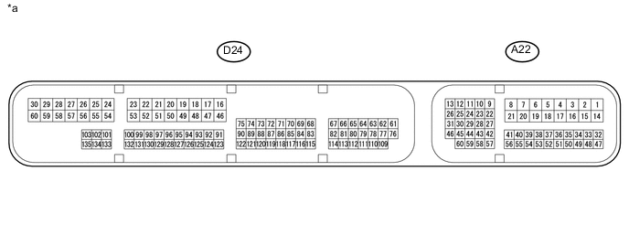
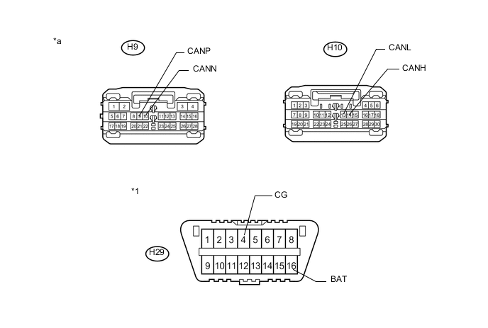
DLC3
-
Disconnect the cable from the negative (-) auxiliary battery terminal.
-
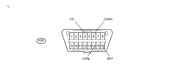
Measure the resistance according to the value(s) in the table below.
Table 21. Text in Illustration *1 DLC3 - - Standard Resistance Terminal No. (Symbol) Wiring Color Terminal Description Condition Specified Condition H29-6 (CANH) - H29-14 (CANL) L - W HIGH-level CAN bus line - LOW-level CAN bus line Cable disconnected from negative (-) auxiliary battery terminal 54 to 69 Ω H29-6 (CANH) - H29-4 (CG) L - W-B HIGH-level CAN bus line - Ground Cable disconnected from negative (-) auxiliary battery terminal 200 Ω or higher H29-14 (CANL) - H29-4 (CG) W - W-B LOW-level CAN bus line - Ground Cable disconnected from negative (-) auxiliary battery terminal 200 Ω or higher H29-6 (CANH) - H29-16 (BAT) L - L HIGH-level CAN bus line - Auxiliary battery positive (+) Cable disconnected from negative (-) auxiliary battery terminal 6 kΩ or higher H29-14 (CANL) - H29-16 (BAT) W - L LOW-level CAN bus line - Auxiliary battery positive (+) Cable disconnected from negative (-) auxiliary battery terminal 6 kΩ or higher
-
-
POWER MANAGEMENT CONTROL ECU
Table 22. Text in Illustration *a Component without harness connected
(Power Management Control ECU)
- -
-
Disconnect the cable from the negative (-) auxiliary battery terminal.
-
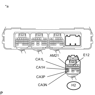
Disconnect the power management control ECU connector.
Table 23. Text in Illustration *a Rear view of wire harness connector
(to Power Management Control ECU)
-
Measure the resistance according to the value(s) in the table below.
Standard Resistance Table 24. V Bus Branch Lines Terminal No. (Symbol) Wiring Color Terminal Description Condition Specified Condition H2-25 (CA1H) - H2-24 (CA1L) B - W HIGH-level CAN bus line - LOW-level CAN bus line Cable disconnected from negative (-) auxiliary battery terminal 54 to 69 Ω H2-25 (CA1H) - H2-4 (E12) B - BR HIGH-level CAN bus line - Ground Cable disconnected from negative (-) auxiliary battery terminal 200 Ω or higher H2-24 (CA1L) - H2-4 (E12) W - BR LOW-level CAN bus line - Ground Cable disconnected from negative (-) auxiliary battery terminal 200 Ω or higher H2-25 (CA1H) - H2-7 (AM21) B - LG HIGH-level CAN bus line - Auxiliary battery positive (+) Cable disconnected from negative (-) auxiliary battery terminal 6 kΩ or higher H2-24 (CA1L) - H2-7 (AM21) W - LG LOW-level CAN bus line - Auxiliary battery positive (+) Cable disconnected from negative (-) auxiliary battery terminal 6 kΩ or higher Standard Resistance Table 25. Sub Bus 15 Main Lines Terminal No. (Symbol) Wiring Color Terminal Description Condition Specified Condition H2-31 (CA3P) - H2-30 (CA3N) R - W HIGH-level CAN bus line - LOW-level CAN bus line Cable disconnected from negative (-) auxiliary battery terminal 108 to 132 Ω H2-31 (CA3P) - H2-4 (E12) R - BR HIGH-level CAN bus line - Ground Cable disconnected from negative (-) auxiliary battery terminal 200 Ω or higher H2-30 (CA3N) - H2-4 (E12) W - BR LOW-level CAN bus line - Ground Cable disconnected from negative (-) auxiliary battery terminal 200 Ω or higher H2-31 (CA3P) - H2-7 (AM21) R - LG HIGH-level CAN bus line - Auxiliary battery positive (+) Cable disconnected from negative (-) auxiliary battery terminal 6 kΩ or higher H2-30 (CA3N) - H2-7 (AM21) W - LG LOW-level CAN bus line - Auxiliary battery positive (+) Cable disconnected from negative (-) auxiliary battery terminal 6 kΩ or higher -
Disconnect the cable from the negative (-) auxiliary battery terminal.
-
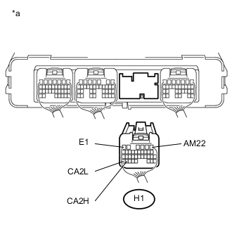
Disconnect the power management control ECU connector.
Table 26. Text in Illustration *a Rear view of wire harness connector
(to Power Management Control ECU)
-
Measure the resistance according to the value(s) in the table below.
Standard Resistance Table 27. Sub Bus 11 Main Lines Terminal No. (Symbol) Wiring Color Terminal Description Condition Specified Condition H1-34 (CA2H) - H1-35 (CA2L) L - LG HIGH-level CAN bus line - LOW-level CAN bus line Cable disconnected from negative (-) auxiliary battery terminal 108 to 132 Ω H1-34 (CA2H) - H1-6 (E1) L - BR HIGH-level CAN bus line - Ground Cable disconnected from negative (-) auxiliary battery terminal 200 Ω or higher H1-35 (CA2L) - H1-6 (E1) LG - BR LOW-level CAN bus line - Ground Cable disconnected from negative (-) auxiliary battery terminal 200 Ω or higher H1-34 (CA2H) - H1-1 (AM22) L - P HIGH-level CAN bus line - Auxiliary battery positive (+) Cable disconnected from negative (-) auxiliary battery terminal 6 kΩ or higher H1-35 (CA2L) - H1-1 (AM22) LG - P LOW-level CAN bus line - Auxiliary battery positive (+) Cable disconnected from negative (-) auxiliary battery terminal 6 kΩ or higher
-
-
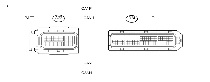
ECM
Table 28. Text in Illustration *a Component without harness connected
(ECM)
- -
-
Disconnect the cable from the negative (-) auxiliary battery terminal.
-
Disconnect the ECM connectors.
Table 29. Text in Illustration *a Front view of wire harness connector
(to ECM)
- - -
Measure the resistance according to the value(s) in the table below.
Standard Resistance Table 30. V Bus Main Lines Terminal No. (Symbol) Wiring Color Terminal Description Condition Specified Condition A22-13 (CANH) - A22-26 (CANL) B - W HIGH-level CAN bus line - LOW-level CAN bus line Cable disconnected from negative (-) auxiliary battery terminal 108 to 132 Ω A22-13 (CANH) - D24-16 (E1) B - BR HIGH-level CAN bus line - Ground Cable disconnected from negative (-) auxiliary battery terminal 200 Ω or higher A22-26 (CANL) - D24-16 (E1) W - BR LOW-level CAN bus line - Ground Cable disconnected from negative (-) auxiliary battery terminal 200 Ω or higher A22-13 (CANH) - A22-1 (BATT) B - GR HIGH-level CAN bus line - Auxiliary battery positive (+) Cable disconnected from negative (-) auxiliary battery terminal 6 kΩ or higher A22-26 (CANL) - A22-1 (BATT) W - GR LOW-level CAN bus line - Auxiliary battery positive (+) Cable disconnected from negative (-) auxiliary battery terminal 6 kΩ or higher Standard Resistance Table 31. Sub Bus 15 Main Lines Terminal No. (Symbol) Wiring Color Terminal Description Condition Specified Condition A22-12 (CANP) - A22-25 (CANN) B - W HIGH-level CAN bus line - LOW-level CAN bus line Cable disconnected from negative (-) auxiliary battery terminal 108 to 132 Ω A22-12 (CANP) - D24-16 (E1) B - BR HIGH-level CAN bus line - Ground Cable disconnected from negative (-) auxiliary battery terminal 200 Ω or higher A22-25 (CANN) - D24-16 (E1) W - BR LOW-level CAN bus line - Ground Cable disconnected from negative (-) auxiliary battery terminal 200 Ω or higher A22-12 (CANP) - A22-1 (BATT) B - GR HIGH-level CAN bus line - Auxiliary battery positive (+) Cable disconnected from negative (-) auxiliary battery terminal 6 kΩ or higher A22-25 (CANN) - A22-1 (BATT) W - GR LOW-level CAN bus line - Auxiliary battery positive (+) Cable disconnected from negative (-) auxiliary battery terminal 6 kΩ or higher
-
-
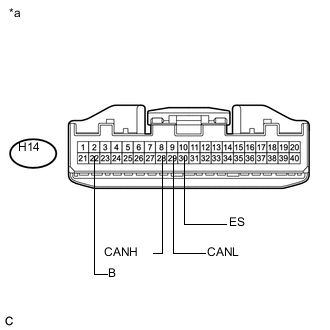
COMBINATION METER ASSEMBLY
Table 32. Text in Illustration *a Component without harness connected
(Combination Meter Assembly)
- -
-
Disconnect the cable from the negative (-) auxiliary battery terminal.
-
Disconnect the combination meter assembly connector.
Table 33. Text in Illustration *a Front view of wire harness connector
(to Combination Meter Assembly)
-
Measure the resistance according to the value(s) in the table below.
Standard Resistance Terminal No. (Symbol) Wiring Color Terminal Description Condition Specified Condition H14-28 (CANH) - H14-29 (CANL) G - W HIGH-level CAN bus line - LOW-level CAN bus line Cable disconnected from negative (-) auxiliary battery terminal 108 to 132 Ω H14-28 (CANH) - H14-30 (ES) G - BR HIGH-level CAN bus line - Ground Cable disconnected from negative (-) auxiliary battery terminal 200 Ω or higher H14-29 (CANL) - H14-30 (ES) W - BR LOW-level CAN bus line - Ground Cable disconnected from negative (-) auxiliary battery terminal 200 Ω or higher H14-28 (CANH) - H14-22 (B) G - W HIGH-level CAN bus line - Auxiliary battery positive (+) Cable disconnected from negative (-) auxiliary battery terminal 6 kΩ or higher H14-29 (CANL) - H14-22 (B) W - W LOW-level CAN bus line - Auxiliary battery positive (+) Cable disconnected from negative (-) auxiliary battery terminal 6 kΩ or higher
-
-
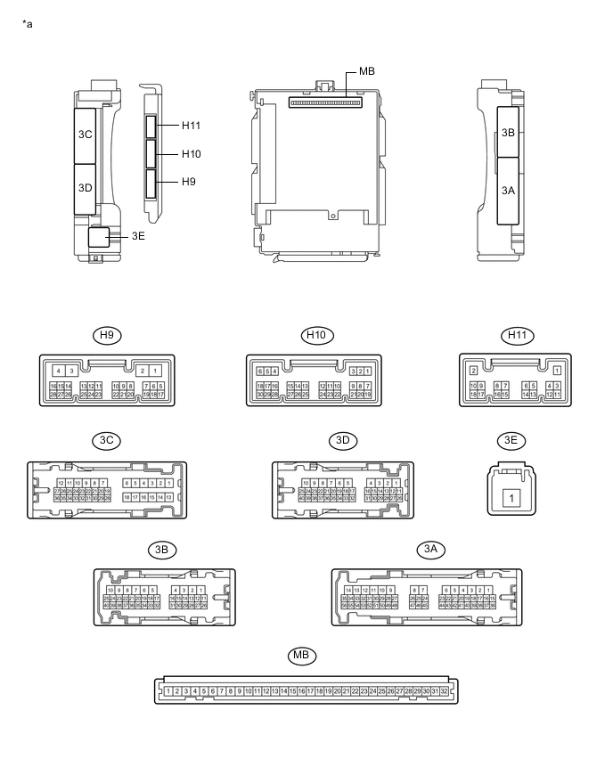
INSTRUMENT PANEL JUNCTION BLOCK ASSEMBLY AND MAIN BODY ECU (MULTIPLEX NETWORK BODY ECU)
Table 34. Text in Illustration *a Component without harness connected
(Instrument Panel Junction Block Assembly and Main Body ECU (Multiplex Network Body ECU))
- -
-
Disconnect the cable from the negative (-) auxiliary battery terminal.
-
Disconnect the main body ECU (multiplex network body ECU) connectors.
Table 35. Text in Illustration *1 DLC3 - - *a Front view of wire harness connector
(to Main Body ECU (Multiplex Network Body ECU))
- - -
Measure the resistance according to the value(s) in the table below.
Standard Resistance Table 36. V Bus Branch Lines Terminal No. (Symbol) Wiring Color Terminal Description Condition Specified Condition H10-14 (CANH) - H10-13 (CANL) V - W HIGH-level CAN bus line - LOW-level CAN bus line Cable disconnected from negative (-) auxiliary battery terminal 54 to 69 Ω H10-14 (CANH) - H29-4 (CG) V - W-B HIGH-level CAN bus line - Ground Cable disconnected from negative (-) auxiliary battery terminal 200 Ω or higher H10-13 (CANL) - H29-4 (CG) W - W-B LOW-level CAN bus line - Ground Cable disconnected from negative (-) auxiliary battery terminal 200 Ω or higher H10-14 (CANH) - H29-16 (BAT) V - L HIGH-level CAN bus line - Auxiliary battery positive (+) Cable disconnected from negative (-) auxiliary battery terminal 6 kΩ or higher H10-13 (CANL) - H29-16 (BAT) W - L LOW-level CAN bus line - Auxiliary battery positive (+) Cable disconnected from negative (-) auxiliary battery terminal 6 kΩ or higher Standard Resistance Table 37. Sub Bus 1 Main Lines Terminal No. (Symbol) Wiring Color Terminal Description Condition Specified Condition H9-9 (CANP) - H9-10 (CANN) Y - GR HIGH-level CAN bus line - LOW-level CAN bus line Cable disconnected from negative (-) auxiliary battery terminal 108 to 132 Ω H9-9 (CANP) - H29-4 (CG) Y - W-B HIGH-level CAN bus line - Ground Cable disconnected from negative (-) auxiliary battery terminal 200 Ω or higher H9-10 (CANN) - H29-4 (CG) GR - W-B LOW-level CAN bus line - Ground Cable disconnected from negative (-) auxiliary battery terminal 200 Ω or higher H9-9 (CANP) - H29-16 (BAT) Y - L HIGH-level CAN bus line - Auxiliary battery positive (+) Cable disconnected from negative (-) auxiliary battery terminal 6 kΩ or higher H9-10 (CANN) - H29-16 (BAT) GR - L LOW-level CAN bus line - Auxiliary battery positive (+) Cable disconnected from negative (-) auxiliary battery terminal 6 kΩ or higher
-
-
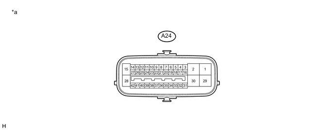
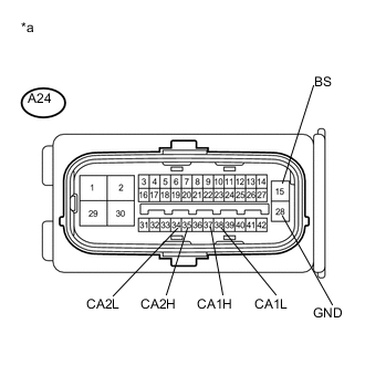
BRAKE BOOSTER WITH MASTER CYLINDER ASSEMBLY (SKID CONTROL ECU)
Table 38. Text in Illustration *a Component without harness connected
(Brake Booster with Master Cylinder Assembly (Skid Control ECU))
- -
-
Disconnect the cable from the negative (-) auxiliary battery terminal.
-
Disconnect the brake booster with master cylinder assembly (skid control ECU) connector.
Table 39. Text in Illustration *a Front view of wire harness connector
(to Brake Booster with Master Cylinder Assembly (Skid Control ECU))
-
Measure the resistance according to the value(s) in the table below.
Standard Resistance Table 40. V Bus Branch Lines Terminal No. (Symbol) Wiring Color Terminal Description Condition Specified Condition A24-37 (CA1H) - A24-38 (CA1L) GR - W HIGH-level CAN bus line - LOW-level CAN bus line Cable disconnected from negative (-) auxiliary battery terminal 54 to 69 Ω A24-37 (CA1H) - A24-28 (GND) GR - W-B HIGH-level CAN bus line - Ground Cable disconnected from negative (-) auxiliary battery terminal 200 Ω or higher A24-38 (CA1L) - A24-28 (GND) W - W-B LOW-level CAN bus line - Ground Cable disconnected from negative (-) auxiliary battery terminal 200 Ω or higher A24-37 (CA1H) - A24-15 (BS) GR - Y HIGH-level CAN bus line - Auxiliary battery positive (+) Cable disconnected from negative (-) auxiliary battery terminal 6 kΩ or higher A24-38 (CA1L) - A24-15 (BS) W - Y LOW-level CAN bus line - Auxiliary battery positive (+) Cable disconnected from negative (-) auxiliary battery terminal 6 kΩ or higher Standard Resistance Table 41. Sub Bus 15 Branch Lines Terminal No. (Symbol) Wiring Color Terminal Description Condition Specified Condition A24-35 (CA2H) - A24-34 (CA2L) B - W HIGH-level CAN bus line - LOW-level CAN bus line Cable disconnected from negative (-) auxiliary battery terminal 54 to 69 Ω A24-35 (CA2H) - A24-28 (GND) B - W-B HIGH-level CAN bus line - Ground Cable disconnected from negative (-) auxiliary battery terminal 200 Ω or higher A24-34 (CA2L) - A24-28 (GND) W - W-B LOW-level CAN bus line - Ground Cable disconnected from negative (-) auxiliary battery terminal 200 Ω or higher A24-35 (CA2H) - A24-15 (BS) B - Y HIGH-level CAN bus line - Auxiliary battery positive (+) Cable disconnected from negative (-) auxiliary battery terminal 6 kΩ or higher A24-34 (CA2L) - A24-15 (BS) W - Y LOW-level CAN bus line - Auxiliary battery positive (+) Cable disconnected from negative (-) auxiliary battery terminal 6 kΩ or higher
-
-
STEERING SENSOR
-
Disconnect the cable from the negative (-) auxiliary battery terminal.
-
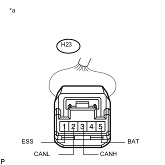
Disconnect the steering sensor connector.
Table 42. Text in Illustration *a Front view of wire harness connector
(to Steering Sensor)
-
Measure the resistance according to the value(s) in the table below.
Standard Resistance Terminal No. (Symbol) Wiring Color Terminal Description Condition Specified Condition H23-3 (CANH) - H23-2 (CANL) P - W HIGH-level CAN bus line - LOW-level CAN bus line Cable disconnected from negative (-) auxiliary battery terminal 54 to 69 Ω H23-3 (CANH) - H23-1 (ESS) P - W-B HIGH-level CAN bus line - Ground Cable disconnected from negative (-) auxiliary battery terminal 200 Ω or higher H23-2 (CANL) - H23-1 (ESS) W - W-B LOW-level CAN bus line - Ground Cable disconnected from negative (-) auxiliary battery terminal 200 Ω or higher H23-3 (CANH) - H23-5 (BAT) P - W HIGH-level CAN bus line - Auxiliary battery positive (+) Cable disconnected from negative (-) auxiliary battery terminal 6 kΩ or higher H23-2 (CANL) - H23-5 (BAT) W - W LOW-level CAN bus line - Auxiliary battery positive (+) Cable disconnected from negative (-) auxiliary battery terminal 6 kΩ or higher
-
-
POWER STEERING ECU WITH MOTOR ASSEMBLY
-
Disconnect the cable from the negative (-) auxiliary battery terminal.
-
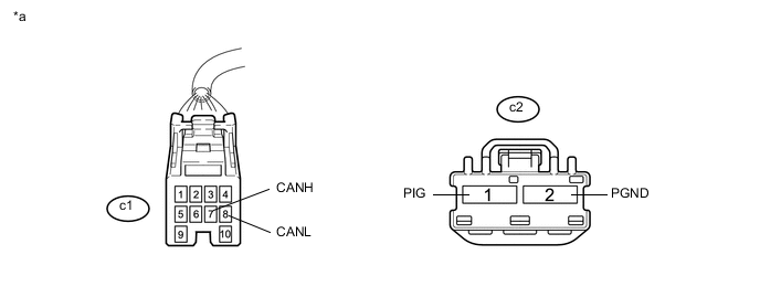
Disconnect the power steering ECU with motor assembly connectors.
Table 43. Text in Illustration *a Component without harness connected
(Power Steering ECU with Motor Assembly)
- - Table 44. Text in Illustration *a Front view of wire harness connector
(to Power Steering ECU with Motor Assembly)
- - -
Measure the resistance according to the value(s) in the table below.
Standard Resistance Terminal No. (Symbol) Wiring Color Terminal Description Condition Specified Condition c1-7 (CANH) - c1-8 (CANL) Y - SB HIGH-level CAN bus line - LOW-level CAN bus line Cable disconnected from negative (-) auxiliary battery terminal 54 to 69 Ω c1-7 (CANH) - c2-2 (PGND) Y - B HIGH-level CAN bus line - Ground Cable disconnected from negative (-) auxiliary battery terminal 200 Ω or higher c1-8 (CANL) - c2-2 (PGND) SB - B LOW-level CAN bus line - Ground Cable disconnected from negative (-) auxiliary battery terminal 200 Ω or higher c1-7 (CANH) - c2-1 (PIG) Y - R HIGH-level CAN bus line - Auxiliary battery positive (+) Cable disconnected from negative (-) auxiliary battery terminal 6 kΩ or higher c1-8 (CANL) - c2-1 (PIG) SB - R LOW-level CAN bus line - Auxiliary battery positive (+) Cable disconnected from negative (-) auxiliary battery terminal 6 kΩ or higher
-
-
AIRBAG SENSOR ASSEMBLY
-
Disconnect the cable from the negative (-) auxiliary battery terminal.
-
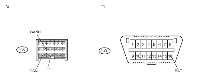
Disconnect the airbag sensor assembly connector.
Table 45. Text in Illustration *1 DLC3 - - *a Front view of wire harness connector
(to Airbag Sensor Assembly)
- - -
Measure the resistance according to the value(s) in the table below.
Standard Resistance Terminal No. (Symbol) Wiring Color Terminal Description Condition Specified Condition H36-13 (CANH) - H36-22 (CANL) Y - W HIGH-level CAN bus line - LOW-level CAN bus line Cable disconnected from negative (-) auxiliary battery terminal 54 to 69 Ω H36-13 (CANH) - H36-25 (E1) Y - W-B HIGH-level CAN bus line - Ground Cable disconnected from negative (-) auxiliary battery terminal 200 Ω or higher H36-22 (CANL) - H36-25 (E1) W - W-B LOW-level CAN bus line - Ground Cable disconnected from negative (-) auxiliary battery terminal 200 Ω or higher H36-13 (CANH) - H29-16 (BAT) Y - L HIGH-level CAN bus line - Auxiliary battery positive (+) Cable disconnected from negative (-) auxiliary battery terminal 6 kΩ or higher H36-22 (CANL) - H29-16 (BAT) W - L LOW-level CAN bus line - Auxiliary battery positive (+) Cable disconnected from negative (-) auxiliary battery terminal 6 kΩ or higher
-
-
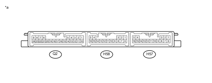
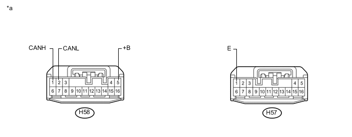
CERTIFICATION ECU (SMART KEY ECU ASSEMBLY)
Table 46. Text in Illustration *a Component without harness connected
(Certification ECU (Smart Key ECU Assembly))
- -
-
Disconnect the cable from the negative (-) auxiliary battery terminal.
-
Disconnect the certification ECU (smart key ECU assembly) connectors.
Table 47. Text in Illustration *a Front view of wire harness connector
(to Certification ECU (Smart Key ECU Assembly))
- - -
Measure the resistance according to the value(s) in the table below.
Standard Resistance Terminal No. (Symbol) Wiring Color Terminal Description Condition Specified Condition H58-1 (CANH) - H58-2 (CANL) V - W HIGH-level CAN bus line - LOW-level CAN bus line Cable disconnected from negative (-) auxiliary battery terminal 54 to 69 Ω H58-1 (CANH) - H57-1 (E) V - W-B HIGH-level CAN bus line - Ground Cable disconnected from negative (-) auxiliary battery terminal 200 Ω or higher H58-2 (CANL) - H57-1 (E) W - W-B LOW-level CAN bus line - Ground Cable disconnected from negative (-) auxiliary battery terminal 200 Ω or higher H58-1 (CANH) - H58-5 (+B) V - R HIGH-level CAN bus line - Auxiliary battery positive (+) Cable disconnected from negative (-) auxiliary battery terminal 6 kΩ or higher H58-2 (CANL) - H58-5 (+B) W - R LOW-level CAN bus line - Auxiliary battery positive (+) Cable disconnected from negative (-) auxiliary battery terminal 6 kΩ or higher
-
-
MULTI-MEDIA MODULE RECEIVER ASSEMBLY (w/ Navigation System)
Table 48. Text in Illustration *a Component without harness connected
(Multi-media Module Receiver Assembly)
- -
-
Disconnect the cable from the negative (-) auxiliary battery terminal.
-
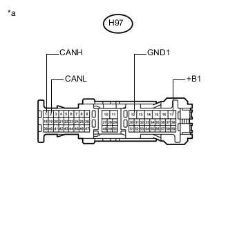
Disconnect the multi-media module receiver assembly connector.
Table 49. Text in Illustration *a Front view of wire harness connector
(to Multi-media Module Receiver Assembly)
-
Measure the resistance according to the value(s) in the table below.
Standard Resistance Terminal No. (Symbol) Wiring Color Terminal Description Condition Specified Condition H97-1 (CANH) - H97-2 (CANL) BE - W HIGH-level CAN bus line - LOW-level CAN bus line Cable disconnected from negative (-) auxiliary battery terminal 54 to 69 Ω H97-1 (CANH) - H97-12 (GND1) BE - W-B HIGH-level CAN bus line - Ground Cable disconnected from negative (-) auxiliary battery terminal 200 Ω or higher H97-2 (CANL) - H97-12 (GND1) W - W-B LOW-level CAN bus line - Ground Cable disconnected from negative (-) auxiliary battery terminal 200 Ω or higher H97-1 (CANH) - H97-17 (+B1) BE - R HIGH-level CAN bus line - Auxiliary battery positive (+) Cable disconnected from negative (-) auxiliary battery terminal 6 kΩ or higher H97-2 (CANL) - H97-17 (+B1) W - R LOW-level CAN bus line - Auxiliary battery positive (+) Cable disconnected from negative (-) auxiliary battery terminal 6 kΩ or higher
-
-
AIR CONDITIONING AMPLIFIER ASSEMBLY
-
Disconnect the cable from the negative (-) auxiliary battery terminal.
-
Disconnect the air conditioning amplifier assembly connector.
Table 50. Text in Illustration *a Component without harness connected
(Air Conditioning Amplifier Assembly)
- - Table 51. Text in Illustration *a Front view of wire harness connector
(to Air Conditioning Amplifier Assembly)
- - -
Measure the resistance according to the value(s) in the table below.
Standard Resistance Terminal No. (Symbol) Wiring Color Terminal Description Condition Specified Condition H54-11 (CANH) - H54-12 (CANL) G - W HIGH-level CAN bus line - LOW-level CAN bus line Cable disconnected from negative (-) auxiliary battery terminal 54 to 69 Ω H54-11 (CANH) - H54-14 (GND) G - W-B HIGH-level CAN bus line - Ground Cable disconnected from negative (-) auxiliary battery terminal 200 Ω or higher H54-12 (CANL) - H54-14 (GND) W - W-B LOW-level CAN bus line - Ground Cable disconnected from negative (-) auxiliary battery terminal 200 Ω or higher H54-11 (CANH) - H54-21 (B) G - GR HIGH-level CAN bus line - Auxiliary battery positive (+) Cable disconnected from negative (-) auxiliary battery terminal 6 kΩ or higher H54-12 (CANL) - H54-21 (B) W - GR LOW-level CAN bus line - Auxiliary battery positive (+) Cable disconnected from negative (-) auxiliary battery terminal 6 kΩ or higher
-
-
CLEARANCE WARNING ECU ASSEMBLY
-
Disconnect the cable from the negative (-) auxiliary battery terminal.
-
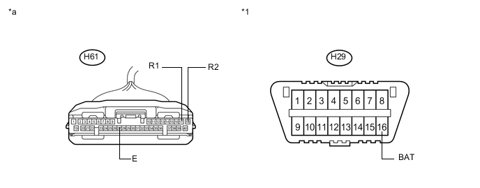
Disconnect the clearance warning ECU assembly connector.
Table 52. Text in Illustration *1 DLC3 - - *a Front view of wire harness connector
(to Clearance Warning ECU Assembly)
- - -
Measure the resistance according to the value(s) in the table below.
Standard Resistance Terminal No. (Symbol) Wiring Color Terminal Description Condition Specified Condition H61-17 (R1) - H61-18 (R2) P - W HIGH-level CAN bus line - LOW-level CAN bus line Cable disconnected from negative (-) auxiliary battery terminal 54 to 69 Ω H61-17 (R1) - H61-27 (E) P - W-B HIGH-level CAN bus line - Ground Cable disconnected from negative (-) auxiliary battery terminal 200 Ω or higher H61-18 (R2) - H61-27 (E) W - W-B LOW-level CAN bus line - Ground Cable disconnected from negative (-) auxiliary battery terminal 200 Ω or higher H61-17 (R1) - H29-16 (BAT) P - L HIGH-level CAN bus line - Auxiliary battery positive (+) Cable disconnected from negative (-) auxiliary battery terminal 6 kΩ or higher H61-18 (R2) - H29-16 (BAT) W - L LOW-level CAN bus line - Auxiliary battery positive (+) Cable disconnected from negative (-) auxiliary battery terminal 6 kΩ or higher
-
-

OUTER MIRROR CONTROL ECU ASSEMBLY LH (w/ Seat Position Memory System)
Table 53. Text in Illustration *a Component without harness connected
(Outer Mirror Control ECU Assembly LH
- -
-
Disconnect the cable from the negative (-) auxiliary battery terminal.
-
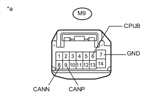
Disconnect the outer mirror control ECU assembly LH connector.
Table 54. Text in Illustration *a Front view of wire harness connector
(to Outer Mirror Control ECU Assembly LH)
-
Measure the resistance according to the value(s) in the table below.
Standard Resistance Terminal No. (Symbol) Wiring Color Terminal Description Condition Specified Condition M9-9 (CANP) - M9-8 (CANN) B - W HIGH-level CAN bus line - LOW-level CAN bus line Cable disconnected from negative (-) auxiliary battery terminal 54 to 69 Ω M9-9 (CANP) - M9-7 (GND) B - W-B HIGH-level CAN bus line - Ground Cable disconnected from negative (-) auxiliary battery terminal 200 Ω or higher M9-8 (CANN) - M9-7 (GND) W - W-B LOW-level CAN bus line - Ground Cable disconnected from negative (-) auxiliary battery terminal 200 Ω or higher M9-9 (CANP) - M9-6 (CPUB) B - W HIGH-level CAN bus line - Auxiliary battery positive (+) Cable disconnected from negative (-) auxiliary battery terminal 6 kΩ or higher M9-8 (CANN) - M9-6 (CPUB) W - W LOW-level CAN bus line - Auxiliary battery positive (+) Cable disconnected from negative (-) auxiliary battery terminal 6 kΩ or higher
-
-

OUTER MIRROR CONTROL ECU ASSEMBLY RH (w/ Seat Position Memory System)
Table 55. Text in Illustration *a Component without harness connected
(Outer Mirror Control ECU Assembly RH)
- -
-
Disconnect the cable from the negative (-) auxiliary battery terminal.
-
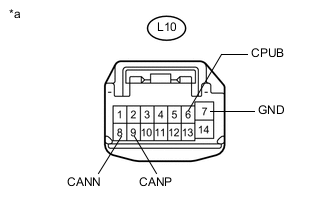
Disconnect the outer mirror control ECU assembly RH connector.
Table 56. Text in Illustration *a Front view of wire harness connector
(to Outer Mirror Control ECU Assembly RH)
-
Measure the resistance according to the value(s) in the table below.
Standard Resistance Terminal No. (Symbol) Wiring Color Terminal Description Condition Specified Condition L10-9 (CANP) - L10-8 (CANN) B - W HIGH-level CAN bus line - LOW-level CAN bus line Cable disconnected from negative (-) auxiliary battery terminal 54 to 69 Ω L10-9 (CANP) - L10-7 (GND) B - W-B HIGH-level CAN bus line - Ground Cable disconnected from negative (-) auxiliary battery terminal 200 Ω or higher L10-8 (CANN) - L10-7 (GND) W - W-B LOW-level CAN bus line - Ground Cable disconnected from negative (-) auxiliary battery terminal 200 Ω or higher L10-9 (CANP) - L10-6 (CPUB) B - W HIGH-level CAN bus line - Auxiliary battery positive (+) Cable disconnected from negative (-) auxiliary battery terminal 6 kΩ or higher L10-8 (CANN) - L10-6 (CPUB) W - W LOW-level CAN bus line - Auxiliary battery positive (+) Cable disconnected from negative (-) auxiliary battery terminal 6 kΩ or higher
-
-

FRONT POWER SEAT SWITCH LH (w/ Seat Position Memory System)
Table 57. Text in Illustration *a Component without harness connected
(Front Power Seat Switch LH)
- -
-
Disconnect the cable from the negative (-) auxiliary battery terminal.
-
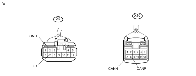
Disconnect the connectors of the front power seat switch LH.
Table 58. Text in Illustration *a Front view of wire harness connector
(to Front Power Seat Switch LH)
- - -
Measure the resistance according to the value(s) in the table below.
Standard Resistance Terminal No. (Symbol) Wiring Color Terminal Description Condition Specified Condition X10-8 (CANP) - X10-7 (CANN) L - W HIGH-level CAN bus line - LOW-level CAN bus line Cable disconnected from negative (-) auxiliary battery terminal 54 to 69 Ω X10-8 (CANP) - X9-2 (GND) L - W-B HIGH-level CAN bus line - Ground Cable disconnected from negative (-) auxiliary battery terminal 200 Ω or higher X10-7 (CANN) - X9-2 (GND) W - W-B LOW-level CAN bus line - Ground Cable disconnected from negative (-) auxiliary battery terminal 200 Ω or higher X10-8 (CANP) - X9-7 (+B) L - R HIGH-level CAN bus line - Auxiliary battery positive (+) Cable disconnected from negative (-) auxiliary battery terminal 6 kΩ or higher X10-7 (CANN) - X9-7 (+B) W - R LOW-level CAN bus line - Auxiliary battery positive (+) Cable disconnected from negative (-) auxiliary battery terminal 6 kΩ or higher
-
-

FRONT POWER SEAT SWITCH RH (w/ Seat Position Memory System)
Table 59. Text in Illustration *a Component without harness connected
(Front Power Seat Switch RH)
- -
-
Disconnect the cable from the negative (-) auxiliary battery terminal.
-

Disconnect the connectors of the front power seat switch RH.
Table 60. Text in Illustration *a Front view of wire harness connector
(to Front Power Seat Switch RH)
- - -
Measure the resistance according to the value(s) in the table below.
Standard Resistance Terminal No. (Symbol) Wiring Color Terminal Description Condition Specified Condition W10-8 (CANP) - W10-7 (CANN) L - W HIGH-level CAN bus line - LOW-level CAN bus line Cable disconnected from negative (-) auxiliary battery terminal 54 to 69 Ω W10-8 (CANP) - W9-2 (GND) L - W-B HIGH-level CAN bus line - Ground Cable disconnected from negative (-) auxiliary battery terminal 200 Ω or higher W10-7 (CANN) - W9-2 (GND) W - W-B LOW-level CAN bus line - Ground Cable disconnected from negative (-) auxiliary battery terminal 200 Ω or higher W10-8 (CANP) - W9-7 (+B) L - R HIGH-level CAN bus line - Auxiliary battery positive (+) Cable disconnected from negative (-) auxiliary battery terminal 6 kΩ or higher W10-7 (CANN) - W9-7 (+B) W - R LOW-level CAN bus line - Auxiliary battery positive (+) Cable disconnected from negative (-) auxiliary battery terminal 6 kΩ or higher
-
-

BLIND SPOT MONITOR SENSOR LH (w/ Blind Spot Monitor System)
Table 61. Text in Illustration *a Component without harness connected
(Blind Spot Monitor Sensor LH)
- -
-
Disconnect the cable from the negative (-) auxiliary battery terminal.
-
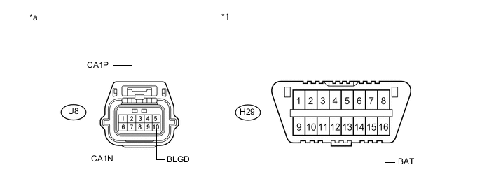
Disconnect the blind spot monitor sensor LH connector.
Table 62. Text in Illustration *1 DLC3 - - *a Front view of wire harness connector
(to Blind Spot Monitor Sensor LH)
- - -
Measure the resistance according to the value(s) in the table below.
Standard Resistance Terminal No. (Symbol) Wiring Color Terminal Description Condition Specified Condition U8-2 (CA1P) - U8-7 (CA1N) B - R HIGH-level CAN bus line - LOW-level CAN bus line Cable disconnected from negative (-) auxiliary battery terminal 54 to 69 Ω U8-2 (CA1P) - U8-10 (BLGD) B - W-B HIGH-level CAN bus line - Ground Cable disconnected from negative (-) auxiliary battery terminal 200 Ω or higher U8-7 (CA1N) - U8-10 (BLGD) R - W-B LOW-level CAN bus line - Ground Cable disconnected from negative (-) auxiliary battery terminal 200 Ω or higher U8-2 (CA1P) - H29-16 (BAT) B - L HIGH-level CAN bus line - Auxiliary battery positive (+) Cable disconnected from negative (-) auxiliary battery terminal 6 kΩ or higher U8-7 (CA1N) - H29-16 (BAT) R - L LOW-level CAN bus line - Auxiliary battery positive (+) Cable disconnected from negative (-) auxiliary battery terminal 6 kΩ or higher
-
-

MULTIPLEX TILT AND TELESCOPIC ECU (w/ Seat Position Memory System or Power Tilt and Power Telescopic Steering Column System)
Table 63. Text in Illustration *a Component without harness connected
(Multiplex Tilt and Telescopic ECU)
- -
-
Disconnect the cable from the negative (-) auxiliary battery terminal.
-
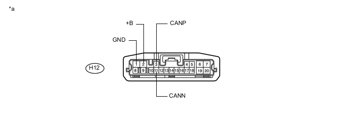
Disconnect the multiplex tilt and telescopic ECU connector.
Table 64. Text in Illustration *a Front view of wire harness connector
(to Multiplex Tilt and Telescopic ECU)
- - -
Measure the resistance according to the value(s) in the table below.
Standard Resistance Terminal No. (Symbol) Wiring Color Terminal Description Condition Specified Condition H12-3 (CANP) - H12-11 (CANN) L - GR HIGH-level CAN bus line - LOW-level CAN bus line Cable disconnected from negative (-) auxiliary battery terminal 54 to 69 Ω H12-3 (CANP) - H12-1 (GND) L - W-B HIGH-level CAN bus line - Ground Cable disconnected from negative (-) auxiliary battery terminal 200 Ω or higher H12-11 (CANN) - H12-1 (GND) GR - W-B LOW-level CAN bus line - Ground Cable disconnected from negative (-) auxiliary battery terminal 200 Ω or higher H12-3 (CANP) - H12-2 (+B) L - Y HIGH-level CAN bus line - Auxiliary battery positive (+) Cable disconnected from negative (-) auxiliary battery terminal 6 kΩ or higher H12-11 (CANN) - H12-2 (+B) GR - Y LOW-level CAN bus line - Auxiliary battery positive (+) Cable disconnected from negative (-) auxiliary battery terminal 6 kΩ or higher
-
-
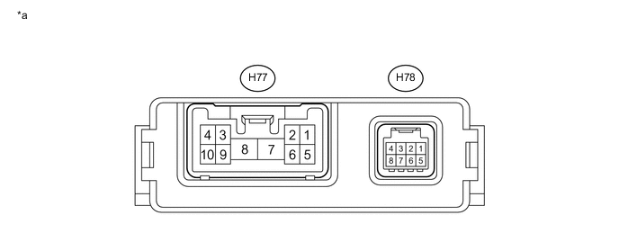
SEAT BELT CONTROL ECU (w/ Dynamic Radar Cruise Control System)
Table 65. Text in Illustration *a Component without harness connected
(Seat Belt Control ECU)
- -
-
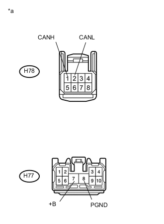
Disconnect the seat belt control ECU connectors.
Table 66. Text in Illustration *a Front view of wire harness connector
(to Seat Belt Control ECU)
-
Measure the resistance according to the value(s) in the table below.
Standard Resistance Terminal No. (Symbol) Wiring Color Terminal Description Condition Specified Condition H78-1 (CANH) - H78-2 (CANL) G - LG HIGH-level CAN bus line - LOW-level CAN bus line Cable disconnected from negative (-) auxiliary battery terminal 54 to 69 Ω H78-1 (CANH) - H77-8 (PGND) G - W-B HIGH-level CAN bus line - Ground Cable disconnected from negative (-) auxiliary battery terminal 200 Ω or higher H78-2 (CANL) - H77-8 (PGND) LG - W-B LOW-level CAN bus line - Ground Cable disconnected from negative (-) auxiliary battery terminal 200 Ω or higher H78-1 (CANH) - H77-7 (+B) G - B HIGH-level CAN bus line - Auxiliary battery positive (+) Cable disconnected from negative (-) auxiliary battery terminal 6 kΩ or higher H78-2 (CANL) - H77-7 (+B) LG - B LOW-level CAN bus line - Auxiliary battery positive (+) Cable disconnected from negative (-) auxiliary battery terminal 6 kΩ or higher
-
-
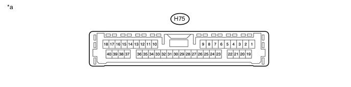
DRIVING SUPPORT ECU ASSEMBLY (w/ Dynamic Radar Cruise Control System)
Table 67. Text in Illustration *a Component without harness connected
(Driving Support ECU Assembly)
- -
-
Disconnect the cable from the negative (-) auxiliary battery terminal.
-
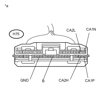
Disconnect the driving support ECU assembly connector.
Table 68. Text in Illustration *a Front view of wire harness connector
(to Driving Support ECU Assembly)
-
Measure the resistance according to the value(s) in the table below.
Standard Resistance Table 69. Sub Bus 11 Branch Lines Terminal No. (Symbol) Wiring Color Terminal Description Condition Specified Condition H75-39 (CA2H) - H75-17 (CA2L) R - LG HIGH-level CAN bus line - LOW-level CAN bus line Cable disconnected from negative (-) auxiliary battery terminal 54 to 69 Ω H75-39 (CA2H) - H75-25 (GND) R - W-B HIGH-level CAN bus line - Ground Cable disconnected from negative (-) auxiliary battery terminal 200 Ω or higher H75-17 (CA2L) - H75-25 (GND) LG - W-B LOW-level CAN bus line - Ground Cable disconnected from negative (-) auxiliary battery terminal 200 Ω or higher H75-39 (CA2H) - H75-30 (B) R - V HIGH-level CAN bus line - Auxiliary battery positive (+) Cable disconnected from negative (-) auxiliary battery terminal 6 kΩ or higher H75-17 (CA2L) - H75-30 (B) LG - V LOW-level CAN bus line - Auxiliary battery positive (+) Cable disconnected from negative (-) auxiliary battery terminal 6 kΩ or higher Standard Resistance Table 70. Sub Bus 13 Main Lines Terminal No. (Symbol) Wiring Color Terminal Description Condition Specified Condition H75-40 (CA1P) - H75-18 (CA1N) B - W HIGH-level CAN bus line - LOW-level CAN bus line Cable disconnected from negative (-) auxiliary battery terminal 108 to 132 Ω H75-40 (CA1P) - H75-25 (GND) B - W-B HIGH-level CAN bus line - Ground Cable disconnected from negative (-) auxiliary battery terminal 200 Ω or higher H75-18 (CA1N) - H75-25 (GND) W - W-B LOW-level CAN bus line - Ground Cable disconnected from negative (-) auxiliary battery terminal 200 Ω or higher H75-40 (CA1P) - H75-30 (B) B - V HIGH-level CAN bus line - Auxiliary battery positive (+) Cable disconnected from negative (-) auxiliary battery terminal 6 kΩ or higher H75-18 (CA1N) - H75-30 (B) W - V LOW-level CAN bus line - Auxiliary battery positive (+) Cable disconnected from negative (-) auxiliary battery terminal 6 kΩ or higher
-
-
MILLIMETER WAVE RADAR SENSOR (w/ Dynamic Radar Cruise Control System)
-
Disconnect the cable from the negative (-) auxiliary battery terminal.
-
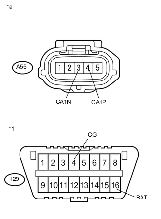
Disconnect the millimeter wave radar sensor connector.
Table 71. Text in Illustration *1 DLC3 *a Front view of wire harness connector
(to Millimeter Wave Radar Sensor)
-
Measure the resistance according to the value(s) in the table below.
Standard Resistance Terminal No. (Symbol) Wiring Color Terminal Description Condition Specified Condition A55-4 (CA1P) - A55-3 (CA1N) B - W HIGH-level CAN bus line - LOW-level CAN bus line Cable disconnected from negative (-) auxiliary battery terminal 108 to 132 Ω A55-4 (CA1P)- H29-4 (CG) B - W-B HIGH-level CAN bus line - Ground Cable disconnected from negative (-) auxiliary battery terminal 200 Ω or higher A55-3 (CA1N) - H29-4 (CG) W - W-B LOW-level CAN bus line - Ground Cable disconnected from negative (-) auxiliary battery terminal 200 Ω or higher A55-4 (CA1P) - H29-16 (BAT) B - L HIGH-level CAN bus line - Auxiliary battery positive (+) Cable disconnected from negative (-) auxiliary battery terminal 6 kΩ or higher A55-3 (CA1N) - H29-16 (BAT) W - L LOW-level CAN bus line - Auxiliary battery positive (+) Cable disconnected from negative (-) auxiliary battery terminal 6 kΩ or higher
-
-
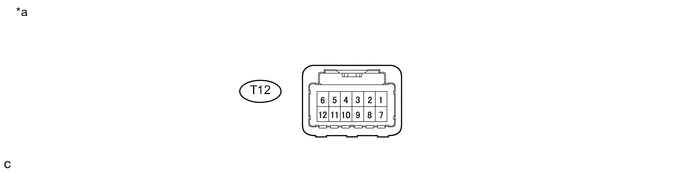
LANE DEPARTURE WARNING CAMERA (for LHD w/ Lane Departure Alert System)
Table 72. Text in Illustration *a Component without harness connected
(Lane Departure Warning Camera)
- -
-
Disconnect the cable from the negative (-) auxiliary battery terminal.
-
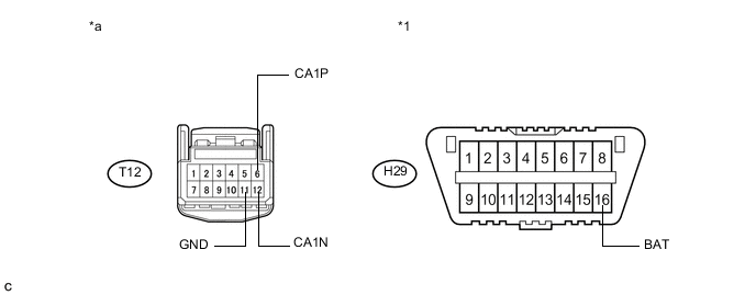
Disconnect the lane departure warning camera connector.
Table 73. Text in Illustration *1 DLC3 - - *a Front view of wire harness connector
(to Lane Departure Warning Camera)
- - -
Measure the resistance according to the value(s) in the table below.
Standard Resistance Terminal No. (Symbol) Wiring Color Terminal Description Condition Specified Condition T12-6 (CA1P) - T12-12 (CA1N) B - W HIGH-level CAN bus line - LOW-level CAN bus line Cable disconnected from negative (-) auxiliary battery terminal 54 to 69 Ω T12-6 (CA1P) - T12-11 (GND) B - W-B HIGH-level CAN bus line - Ground Cable disconnected from negative (-) auxiliary battery terminal 200 Ω or higher T12-12 (CA1N) - T12-11 (GND) W - W-B LOW-level CAN bus line - Ground Cable disconnected from negative (-) auxiliary battery terminal 200 Ω or higher T12-6 (CA1P) - H29-16 (BAT) B - L HIGH-level CAN bus line - Auxiliary battery positive (+) Cable disconnected from negative (-) auxiliary battery terminal 6 kΩ or higher T12-12 (CA1N) - H29-16 (BAT) W - L LOW-level CAN bus line - Auxiliary battery positive (+) Cable disconnected from negative (-) auxiliary battery terminal 6 kΩ or higher
-
-

LUGGAGE CLOSER MOTOR ASSEMBLY (w/ Power Trunk Lid System)
Table 74. Text in Illustration *a Component without harness connected
(Luggage Closer Motor Assembly)
- -
-
Disconnect the cable from the negative (-) auxiliary battery terminal.
-
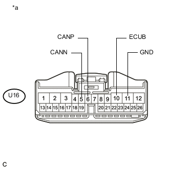
Disconnect the luggage closer motor assembly connector.
Table 75. Text in Illustration *a Front view of wire harness connector
(to Luggage Closer Motor Assembly)
-
Measure the resistance according to the value(s) in the table below.
Standard Resistance Terminal No. (Symbol) Wiring Color Terminal Description Condition Specified Condition U16-6 (CANP) - U16-5 (CANN) V - GR HIGH-level CAN bus line - LOW-level CAN bus line Cable disconnected from negative (-) auxiliary battery terminal 54 to 69 Ω U16-6 (CANP) - U16-11 (GND) V - W-B HIGH-level CAN bus line - Ground Cable disconnected from negative (-) auxiliary battery terminal 200 Ω or higher U16-5 (CANN) - U16-11 (GND) GR - W-B LOW-level CAN bus line - Ground Cable disconnected from negative (-) auxiliary battery terminal 200 Ω or higher U16-6 (CANP) - U16-10 (ECUB) V - W HIGH-level CAN bus line - Auxiliary battery positive (+) Cable disconnected from negative (-) auxiliary battery terminal 6 kΩ or higher U16-5 (CANN) - U16-10 (ECUB) GR - W LOW-level CAN bus line - Auxiliary battery positive (+) Cable disconnected from negative (-) auxiliary battery terminal 6 kΩ or higher
-