| DTC Code | DTC Name |
|---|---|
| C1AB3 | Short to GND in Outer Mirror Indicator(Slave) |
DESCRIPTION
This DTC is stored when the blind spot monitor sensor RH detects a ground short in the outer rear view mirror indicator RH.
| DTC No. | DTC Detection Condition | Trouble Area |
|---|---|---|
| C1AB3 |
|
|
CAUTION / NOTICE / HINT
When checking for DTCs, make sure that the blind spot monitor main switch (warning canceling switch assembly) is on.
PROCEDURE
- Click here
CHECK DTC
-
Clear the DTCs (Click here).
-
Recheck for DTCs and check if the same DTC is output again.
OK No DTCs are output.
- OK
USE SIMULATION METHOD TO CHECK (Click here)
- NGClick here
-
- Click here
CHECK HARNESS AND CONNECTOR (BLIND SPOT MONITOR SENSOR RH - OUTER MIRROR CONTROL ECU ASSEMBLY RH)
-
Disconnect the U9 blind spot monitor sensor RH connector.
-
Disconnect the L10 outer mirror control ECU assembly RH connector.
-
Measure the resistance according to the value(s) in the table below.
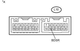
Standard Resistance Tester Connection Condition Specified Condition L10-13 (BDSR) - Body ground Always 10 kΩ or higher
- OKClick here
- NG
REPAIR OR REPLACE HARNESS OR CONNECTOR
-
- Click here
CHECK HARNESS AND CONNECTOR (OUTER REAR VIEW MIRROR ASSEMBLY RH - OUTER MIRROR CONTROL ECU ASSEMBLY RH)
-
Disconnect the z11 outer mirror control ECU assembly RH connector.
-
Disconnect the IND1 outer rear view mirror RH connector.
-
Measure the resistance according to the value(s) in the table below.
Standard Resistance Tester Connection Condition Specified Condition z11-8 (BSM) - Body ground Always 10 kΩ or higher
- OKClick here
- NG
REPLACE OUTER REAR VIEW MIRROR ASSEMBLY RH (Click here)
-
- Click here
INSPECT OUTER MIRROR CONTROL ECU ASSEMBLY RH
-
Disconnect the L10 outer mirror control ECU assembly RH connector.
-
Measure the resistance according to the value(s) in the table below.
Standard Resistance Tester Connection Condition Specified Condition L10-13 (BDSR) - Body ground Always 10 kΩ or higher Table 1. Text in Illustration *a Component without harness connected
(Outer Mirror Control ECU Assembly RH)
- OKClick here
- NG
REPLACE OUTER MIRROR CONTROL ECU ASSEMBLY RH (Click here)
-
- Click here
REPLACE OUTER REAR VIEW MIRROR RH
-
Replace the outer rear view mirror RH (Click here).
- NEXTClick here
-
- Click here
CHECK DTC
-
Clear the DTCs (Click here).
-
Recheck for DTCs and check if the same DTC is output again.
OK No DTCs are output.
- OK
END (OUTER REAR VIEW MIRROR RH WAS DEFECTIVE)
- NG
REPLACE BLIND SPOT MONITOR SENSOR RH (Click here)
-