Click here
-
GENERAL
-
This system has a rear television camera assembly mounted on the luggage compartment door to display an image of the area behind the vehicle on the display. The display panel also shows a composite view consisting of the area behind the vehicle and parking guide lines to assist the driver in parking the vehicle by monitoring the area behind the vehicle.
-
This system consists of the following components:
-
Rear television camera assembly
-
Multi-media module receiver assembly
-
Multi-display assembly
-
Spiral cable with sensor sub-assembly
-
Brake booster with master cylinder assembly (skid control ECU)
-
Power management control ECU
-
Main body ECU (multiplex network body ECU)
-
Luggage closer motor assembly*1
-
*1: w/ Power Trunk Lid System
-
-
-
This system is equipped with a self-diagnosis system, which is operated on a designated window that appears on the multi-display assembly.
-
-
FUNCTION OF COMPONENTS
-
The multi-media module receiver assembly controls the system by using information from the following components.
Item Function Rear Television Camera Assembly
-
Mounted on the luggage compartment door to transmit an image of the area behind the vehicle to the multi-media module receiver assembly.
-
Has a color video camera that uses a Complementary Metal Oxide Semiconductor (CMOS) and wide-angle lens.
Multi-media Module Receiver Assembly
-
Receives video signals, which contain an image of the area behind the vehicle taken with the rear television camera assembly.
-
Performs overall control of the system by receiving signals from the sensors.
-
Creates images and displays adjustment screens performed in the diagnostic mode.
-
Stops displaying the guide lines and buttons and displays "Check surrounding for safety" when an open signal is received for the luggage compartment door.
-
Displays "Back door is open. Do not use the rear view monitor when the back door is not completely closed." on the back camera position setting screen when an open signal is received for the luggage compartment door.
-
Performs control of the system by receiving the reverse signal from the power management control ECU.
Multi-display Assembly Receives the video signals containing a composite of an image of the area behind the vehicle and parking assist guideline signals from the multi-media module receiver assembly, and displays them on the display panel. Spiral Cable with Sensor Sub-assembly Detects the angle of the steering wheel and transmits the resulting signals to the multi-media module receiver assembly through CAN communication. Power Management Control ECU Transmits a reverse signal to the multi-media module receiver assembly through CAN communication. Brake Booster with Master Cylinder Assembly (Skid Control ECU) Transmits a vehicle speed signal to the multi-media module receiver assembly through CAN communication. Main Body ECU (Multiplex Network Body ECU)
-
Transmits a vehicle information signal to the multi-media module receiver assembly through CAN communication.
-
Transmits a luggage compartment door courtesy switch signal to the multi-media module receiver assembly via CAN communication.
Luggage Closer Motor Assembly*1 Transmits a luggage compartment door courtesy switch signal to the main body ECU (multiplex network body ECU) through CAN communication.
-
*1: w/ Power Trunk Lid System
-
-
-
OPERATION EXPLANATION
-
The multi-media module receiver assembly receives the reverse signal when the power switch is on (IG) and the shift lever is moved to R. After receiving the reverse signal, the multi-display assembly switches to the parking assist monitor system.
-
-
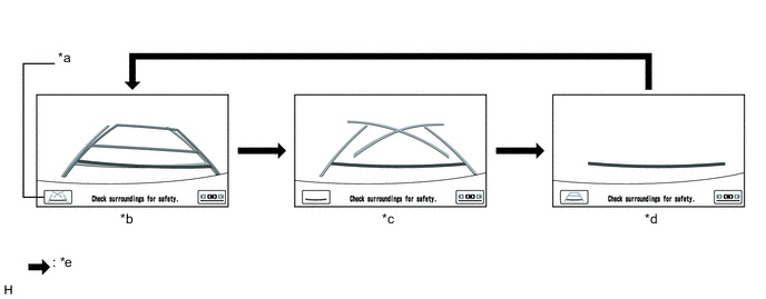
DISPLAY MODE SETTING
Table 1. Text in Illustration *a Display Mode Switch Screen Button *b Estimated Course Line Display Mode *c Parking Assist Guide Line Display Mode *d Distance Guide Line Display Mode *e Display Mode Switch Screen Button Pressed - -
-
While the parking assist monitor is displayed on the multi-display assembly, pressing the display mode switch screen button switches the parking assist monitor display mode.
Table 2. Parking Assist Monitor Display Mode Parking Assist Monitor Display Mode Distance Guide Lines
(Red)
Distance Guide Line
(Blue)
Vehicle Width Extension Guide Line
(Blue)
Estimated Course Lines
(Yellow)
Parking Assist Guide Lines
(Blue)
Estimated course line display mode Displayed Displayed Displayed Displayed Not displayed Parking assist guide line display mode Displayed Not displayed Displayed Not displayed Displayed Distance guide line display mode Displayed Not displayed Not displayed Not displayed Not displayed
-
-
DIAGNOSTIC FUNCTION OUTLINE
-
This parking assist monitor system has a diagnostic function displayed on the multi-display assembly. This function enables calibration (adjustment and verification) of the parking assist monitor system (Click here).
-
The following items for the parking assist monitor system can be checked using the GTS.
Item Proceed to DTC Data List / Active Test
-