Click here
-
REAR TELEVISION CAMERA ASSEMBLY
-

Disconnect the U6 rear television camera assembly connector.
-
Measure the voltage on the wire harness side connector according to the value(s) in the table below.
Terminal No. (Symbol) Wiring Color Terminal Description Condition Specified Condition U6-6 (CB+) - Body ground B - Body ground Power source Power switch on (ACC) 5.5 to 7.05 V If the result is not as specified, there may be a malfunction on the wire harness side.
-
Reconnect the U6 rear television camera assembly connector.
-
Measure the voltage and check for pulses at each terminal of the connector.
Terminal No. (Symbol) Wiring Color Terminal Description Condition Specified Condition U6-3 (CV+) - U6-2 (CV-) W - R Video signal Power switch on (IG)
Shift lever in R
Camera lens not covered, displaying image
Pulse generation
(See waveform 1)
Power switch on (IG)
Shift lever in R
Camera lens covered, blacking out screen
Pulse generation
(See waveform 2)
U6-5 (CGND) - Body ground BR - Body ground Shield ground Always Below 1 V Tip:A waterproof connector is used for the rear television camera assembly. Therefore, inspect the waveform at the multi-media module receiver assembly with the connector connected.
If the result is not as specified, the rear television camera assembly may have a malfunction.
-
Reference (Oscilloscope waveform):
Tip:A waterproof connector is used for the rear television camera assembly. Therefore, inspect the waveform at the multi-media module receiver assembly with the connector connected.
-
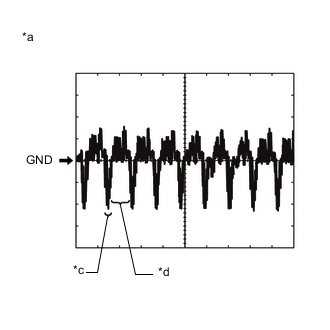
Waveform 1 (camera lens is not covered, displaying an image)
Item Content Measurement terminal U6-3 (CV+) - U6-2 (CV-) Measurement setting 200 mV/DIV., 50 μs./DIV. Condition Power switch on (IG), shift lever in R Tip:
-
The video waveform changes according to the image sent by the rear television camera assembly.
-
The video waveform is constantly output when the power switch is on (ACC).
-
-
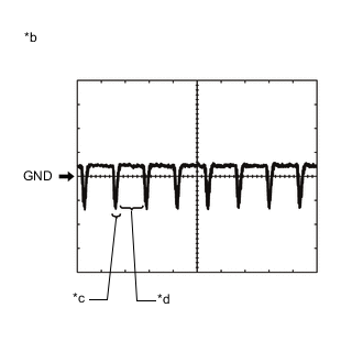
Waveform 2 (camera lens is covered, blacking out the screen)
Item Content Measurement terminal U6-3 (CV+) - U6-2 (CV-) Measurement setting 200 mV/DIV., 50 μs./DIV. Condition Power switch on (IG), shift lever in R Tip:
-
The video waveform changes according to the image sent by the rear television camera assembly.
-
The video waveform is constantly output when the power switch is on (ACC).
Table 1. Text in Illustration *a Waveform 1 (camera lens is not covered, displaying an image) *b Waveform 2 (camera lens is covered, blacking out the screen) *c Synchronization Signal *d Video Waveform -
-
-
-
MULTI-MEDIA MODULE RECEIVER ASSEMBLY (Click here)