AMBIENT TEMPERATURE SENSOR INSPECTION
PROCEDURE
-
INSPECT AMBIENT TEMPERATURE SENSOR (THERMISTOR ASSEMBLY)
-
Measure the resistance according to the value(s) in the table below.
Standard Resistance Tester Connection Condition Specified Condition 1 (-) - 2 (+) 10°C (50°F) 3.00 to 3.73 kΩ 1 (-) - 2 (+) 15°C (59°F) 2.45 to 2.88 kΩ 1 (-) - 2 (+) 20°C (68°F) 1.95 to 2.30 kΩ 1 (-) - 2 (+) 25°C (77°F) 1.60 to 1.80 kΩ 1 (-) - 2 (+) 30°C (86°F) 1.28 to 1.47 kΩ 1 (-) - 2 (+) 35°C (95°F) 1.00 to 1.22 kΩ 1 (-) - 2 (+) 40°C (104°F) 0.80 to 1.00 kΩ 1 (-) - 2 (+) 45°C (113°F) 0.65 to 0.85 kΩ 1 (-) - 2 (+) 50°C (122°F) 0.50 to 0.70 kΩ 1 (-) - 2 (+) 55°C (131°F) 0.44 to 0.60 kΩ 1 (-) - 2 (+) 60°C (140°F) 0.36 to 0.50 kΩ Note
-
Hold the sensor only by its connector. Touching the sensor may change the resistance value.
-
When measuring, the sensor temperature must be the same as the ambient temperature.
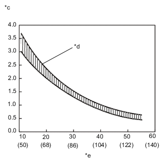
Tech Tips
As the temperature increases, the resistance decreases (see the graph).
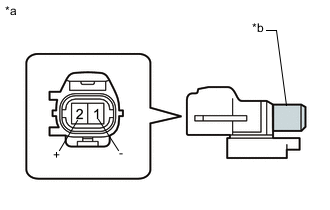
Text in Illustration *a Component without harness connected
(Ambient Temperature Sensor (Thermistor Assembly))
*b Sensing Portion *c Resistance (kΩ) *d Allowable Range *e Temperature (°C (°F)) If the resistance is not as specified, replace the ambient temperature sensor (thermistor assembly).
-
-