CONDENSER INSTALLATION
PROCEDURE
-
INSTALL COOLER CONDENSER ASSEMBLY
-
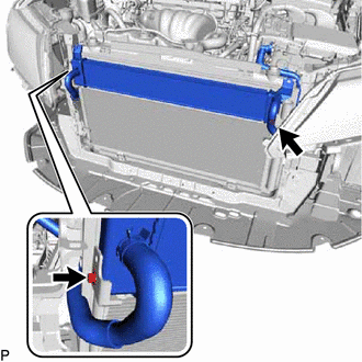
Temporarily install the cooler condenser assembly to the radiator assembly with the 2 bolts.
-
Insert the cooler condenser assembly with radiator assembly.
-
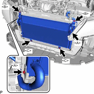
Temporarily install the 2 bolts <B> and 2 bolts <C>.
-
Install the cooler condenser assembly with the 2 bolts <A>, 2 bolts <B> and 2 bolts <C>.
- Torque:
- Bolt <A>
- 9.0 N*m { 92 kgf*cm, 80 in.*lbf }
- Bolt <B>, <C>
- 5.0 N*m { 51 kgf*cm, 44 in.*lbf }
Tech Tips
If the cooler condenser assembly is replaced with a new one, add compressor oil to the new cooler condenser assembly.
Capacity 40 cc (1.4 fl. oz.) Compressor oil ND-OIL 11 or equivalent
-
-
CONNECT AIR CONDITIONER TUBE AND ACCESSORY ASSEMBLY
-
Remove the vinyl tape from the air conditioner tube and accessory assembly and the connector part of the cooler condenser assembly.
-
Sufficiently apply compressor oil to a new O-ring and the fitting surface of the tube joint.
Compressor oil ND-OIL 11 or equivalent -
Install the O-ring to the air conditioner tube and accessory assembly.
-
Install the air conditioner tube and accessory assembly to the cooler condenser assembly with the bolt.
- Torque:
- 9.8 N*m { 100 kgf*cm, 87 in.*lbf }
-
-
CONNECT NO. 1 COOLER REFRIGERANT DISCHARGE HOSE
-
Remove the attached vinyl tape from the No. 1 cooler refrigerant discharge hose and the connecting part of the cooler condenser assembly.
-
Sufficiently apply compressor oil to a new O-ring and the fitting surface of the hose joint.
Compressor oil ND-OIL 11 or equivalent -
Install the O-ring to the No. 1 cooler refrigerant discharge hose.
-
Install the No. 1 cooler refrigerant discharge hose to the cooler condenser assembly with the bolt.
- Torque:
- 9.8 N*m { 100 kgf*cm, 87 in.*lbf }
-
-
INSTALL RADIATOR SIDE DEFLECTOR LH
-
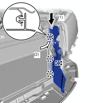
Engage the guide and 3 claws to install the radiator side deflector LH as shown in the illustration.
-
-
INSTALL RADIATOR SIDE DEFLECTOR RH
-
INSTALL HOOD LOCK SUPPORT SUB-ASSEMBLY
-
Install the hood lock support sub-assembly with the bolt.
-
Engage the clamp.
-
Connect the connector.
-
-
INSTALL UPPER RADIATOR SUPPORT
-
INSTALL HOOD LOCK ASSEMBLY
-
INSTALL MILLIMETER WAVE RADAR SENSOR ASSEMBLY (w/ Dynamic Radar Cruise Control System)
-
INSTALL NO. 5 INVERTER BRACKET
-
INSTALL INLET AIR CLEANER ASSEMBLY
-
INSTALL FRONT BUMPER REINFORCEMENT SUB-ASSEMBLY
-
INSTALL FRONT BUMPER ENERGY ABSORBER
-
INSTALL FRONT BUMPER ASSEMBLY
-
CONNECT CABLE TO NEGATIVE AUXILIARY BATTERY TERMINAL
Note
When disconnecting the cable, some systems need to be initialized after the cable is reconnected Click here.
-
INSTALL LUGGAGE TRIM SERVICE HOLE COVER
-
CHARGE AIR CONDITIONING SYSTEM WITH REFRIGERANT
-
WARM UP COMPRESSOR
-
INSPECT FOR REFRIGERANT LEAK
-
ADJUST HOOD SUB-ASSEMBLY