G-BOOK SYSTEM Emergency Call Switch Illumination Circuit
WIRING DIAGRAM
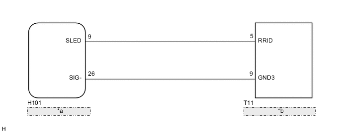
| *a | Telematics Transceiver |
| *b | Roof Console Box Assembly |
CAUTION / NOTICE / HINT
Note
Depending on the parts that are replaced during vehicle inspection or maintenance, performing initialization, registration or calibration may be needed. Refer to Precautions for G-BOOK Click here.
PROCEDURE
-
INSPECT HARNESS AND CONNECTOR (TELEMATICS TRANSCEIVER - ROOF CONSOLE BOX ASSEMBLY)
-
Disconnect the H101 telematics transceiver connector.
-
Disconnect the T11 roof console box assembly connector.
-
Measure the resistance according to the value(s) in the table below.
Standard Resistance Tester Connection Condition Specified Condition H101-9 (SLED) - T11-5 (RRID) Always Below 1 Ω H101-26 (SIG-) - T11-9 (GND3) Always Below 1 Ω H101-9 (SLED) - Body ground Always 10 kΩ or higher H101-26 (SIG-) - Body ground Always 10 kΩ or higher
NG 
REPAIR OR REPLACE HARNESS OR CONNECTOR
OK 
-
-
INSPECT ROOF CONSOLE BOX ASSEMBLY
-
Disconnect the T11 roof console box assembly connector.
-
Connect 4 1.5 V dry-cell batteries in series.
-
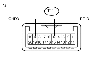
Text in Illustration *a Component without harness connected
(Roof Console Box Assembly)
Connect the positive lead from the batteries to terminal T11-5 (RRID), and the negative lead to terminal T11-9 (GND3) of the roof console box assembly connector.
-
Check if the illumination for the emergency call switch comes on.
OK Illumination for the emergency call switch comes on.
OK
REPLACE TELEMATICS TRANSCEIVER Click here
NG
REPLACE ROOF CONSOLE BOX ASSEMBLY Click here
-