NAVIGATION SYSTEM Stereo Jack Adapter Light does not Illuminate
DESCRIPTION
Power is supplied to the No. 1 stereo jack adapter assembly illumination from the radio receiver assembly.
WIRING DIAGRAM
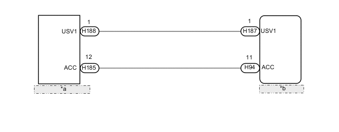
| *a | No. 1 Stereo Jack Adapter Assembly |
| *b | Radio Receiver Assembly |
CAUTION / NOTICE / HINT
Note
Depending on the parts that are replaced during vehicle inspection or maintenance, performing initialization, registration or calibration may be needed. Refer to Precaution for Navigation System.
PROCEDURE
-
CHECK HARNESS AND CONNECTOR (NO. 1 STEREO JACK ADAPTER ASSEMBLY ILLUMINATION POWER SOURCE)
-
Disconnect the H188 and H185 No. 1 stereo jack adapter assembly connectors.
-
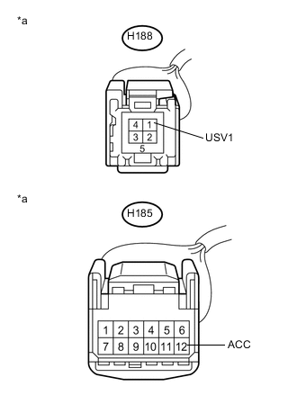
*a Front view of wire harness connector
(to No. 1 Stereo Jack Adapter Assembly)
Measure the voltage according to the value(s) in the table below.
Standard Voltage Tester Connection Condition Specified Condition H188-1 (USV1) - Body ground Power switch on (ACC) 5 V H185-12 (ACC) - Body ground Power switch on (ACC) 11 to 14 V Result Proceed to OK NG
OK 
REPLACE NO. 1 STEREO JACK ADAPTER ASSEMBLY Click here
NG 
-
-
CHECK HARNESS AND CONNECTOR (RADIO RECEIVER ASSEMBLY - NO. 1 STEREO JACK ADAPTER ASSEMBLY)
-
Disconnect the H164 radio receiver assembly connector (for LHD).
Disconnect the H172 radio receiver assembly connector (for RHD).
-
Disconnect the H176 No. 1 stereo jack adapter assembly connector.
-
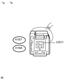
*a Front view of wire harness connector
(to Radio Receiver Assembly)
*b Front view of wire harness connector
(to No. 1 Stereo Jack Adapter Assembly)
Measure the resistance according to the value(s) in the table below.
Standard Resistance Tester Connection Condition Specified Condition H188-1 (USV1) - H187-1 (USV1) Always Below 1 Ω H188-1 (USV1) or H187-1 (USV1) - Body ground Always 10 kΩ or higher Result Proceed to OK NG
NG
REPAIR OR REPLACE HARNESS OR CONNECTOR
OK
-
-
CHECK HARNESS AND CONNECTOR (RADIO RECEIVER ASSEMBLY - NO. 1 STEREO JACK ADAPTER ASSEMBLY)
-
Disconnect the H94 radio receiver assembly connector.
-
Disconnect the H185 No. 1 stereo jack adapter assembly connector.
-
Measure the resistance according to the value(s) in the table below.
Standard Resistance Tester Connection Condition Specified Condition H94-11 (ACC) - H185-12 (ACC) Always Below 1 Ω H94-11 (ACC) or H185-12 (ACC) - Body ground Always 10 kΩ or higher Result Proceed to OK NG
OK
REPLACE RADIO RECEIVER ASSEMBLY Click here
NG
REPAIR OR REPLACE HARNESS OR CONNECTOR
-