| DTC Code | DTC Name |
|---|---|
| B15DB | Telematics Transceiver Disconnected |
DESCRIPTION
If the multi-media module receiver assembly cannot detect the telematics transceiver for a certain period of time (15 seconds) after the power switch is turned on (ACC) and the multi-media module receiver assembly confirms that the information is missing by checking past telematics transceiver recognition information (registered information), this DTC will be stored.
The G-BOOK system uses USB communication between devices. If an open, short, short to +B or short to ground occurs in the USB circuit, communication is interrupted and the G-BOOK system will not operate normally.
| DTC No. | DTC Detection Condition | Trouble Area |
|---|---|---|
| B15DB | Telematics transceiver disconnected |
|
This DTC may be stored due to environmental reasons such as electrical noise or interference.
CAUTION / NOTICE / HINT
-
Inspect the fuses for circuits related to this system before performing the following inspection procedure.
-
Depending on the parts that are replaced during vehicle inspection or maintenance, performing initialization, registration or calibration may be needed. Refer to Precautions for Navigation System (Click here).
PROCEDURE
- Click here
CHECK CONNECTION
-
Check the G-BOOK connection.
-
Turn the power switch on (IG) and wait 1 minute.
-
Select "Main Menu" on the Information screen.
-
Select "G-BOOK.com" on the Main Menu screen.
-
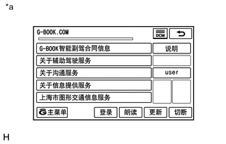
Check that "G-BOOK.com" is displayed.
Tip:If the "G-BOOK.com" screen is displayed, select "Renew" to check if it is possible to access G-BOOK.com.
Result Result Proceed to G-BOOK.com cannot be accessed A G-BOOK.com can be accessed B Tip:
-
This DTC may be stored due to environmental reasons such as electrical noise or interference.
-
If G-BOOK.com can be accessed, clear history DTCs.
Table 1. Text in Illustration *a Example -
-
- AClick here
- B
USE SIMULATION METHOD TO CHECK (Click here)
-
- Click here
CHECK DTC
-
Clear the DTCs (Click here).
-
Recheck for DTCs and check that no DTCs are output.
OK No DTCs are output.
- OK
END
- NGClick here
-
- Click here
CHECK HARNESS AND CONNECTOR (TELEMATICS TRANSCEIVER POWER SOURCE)
-
Disconnect the H101 telematics transceiver connector.
-
Measure the resistance according to the value(s) in the table below.
Standard Resistance Tester Connection Condition Specified Condition H101-4 (E) - Body ground Always Below 1 Ω -
Measure the voltage according to the value(s) in the table below.
Standard Voltage Tester Connection Condition Specified Condition H101-1 (+B) - Body ground Power switch off 11 to 14 V H101-7 (IG2) - Body ground Power switch on (IG) 11 to 14 V H101-8 (ACC) - Body ground Power switch on (ACC) 11 to 14 V
- OKClick here
- NG
REPAIR OR REPLACE HARNESS OR CONNECTOR
-
- Click here
INSPECT MULTI-MEDIA MODULE RECEIVER ASSEMBLY
-
Disconnect the H158 multi-media module receiver assembly connector.
-
Measure the resistance according to the value(s) in the table below.
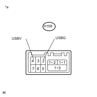
Standard Resistance Tester Connection Condition Specified Condition H158-2 (USBG) - Body ground Always Below 1 Ω -
Measure the voltage according to the value(s) in the table below.
Standard Voltage Tester Connection Condition Specified Condition H158-4 (USBV) - H158-2 (USBG) Power switch on (IG) 4.75 to 5.25 V Table 2. Text in Illustration *a Component without harness connected
(Multi-media Module Receiver Assembly)
- OKClick here
- NG
REPLACE MULTI-MEDIA MODULE RECEIVER ASSEMBLY (Click here)
-
- Click here
CHECK HARNESS AND CONNECTOR (MULTI-MEDIA MODULE RECEIVER ASSEMBLY - TELEMATICS TRANSCEIVER)
-
Check the installation condition.
-
Check the USB communication cable (digital communication cable) between the multi-media module receiver assembly and telematics transceiver for any installation or connection problems.
-
-
Disconnect the H158 multi-media module receiver assembly connector.
-
Disconnect the H159 telematics transceiver connector.
-
Measure the resistance according to the value(s) in the table below.
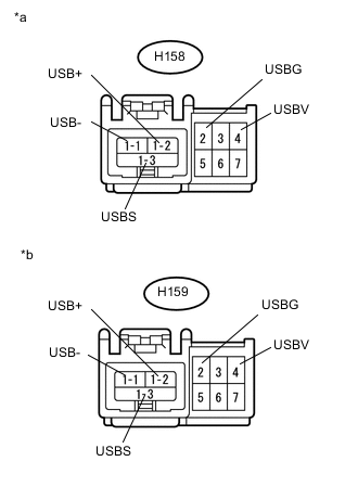
Standard Resistance Tester Connection Condition Specified Condition H158-4 (USBV) - H159-4 (USBV) Always Below 1 Ω H158-2 (USBG) - H159-2 (USBG) Always Below 1 Ω H158-4 (USBV) - Body ground Always 10 kΩ or higher H158-2 (USBG) - Body ground Always 10 kΩ or higher Standard Resistance (USB Cable) Tester Connection Condition Specified Condition H158-1-2 (USB+) - H159-1-2 (USB+) Always Below 1 Ω H158-1-1 (USB-) - H159-1-1 (USB-) Always Below 1 Ω H158-1-3 (USBS) - H159-1-3 (USBS) Always Below 1 Ω H159-1-2 (USB+) - Body ground Always 10 kΩ or higher H159-1-1 (USB-) - Body ground Always 10 kΩ or higher H159-1-3 (USBS) - Body ground Always 10 kΩ or higher Table 3. Text in Illustration *a Component without harness connected
(Multi-media Module Receiver Assembly)
*b Component without harness connected
(Telematics Transceiver)
- OKClick here
- NG
REPAIR OR REPLACE HARNESS OR CONNECTOR
-
- Click here
REPLACE TELEMATICS TRANSCEIVER
-
Replace the telematics transceiver with a known good one and check if the same DTC is output again (Click here).
-
Clear the DTCs (Click here).
-
Recheck for DTCs and check that no DTCs are output.
OK No DTCs are output.
-
- OK
END
- NG
REPLACE MULTI-MEDIA MODULE RECEIVER ASSEMBLY (Click here)
-