| DTC Code | DTC Name |
|---|---|
| Display does not Dim when Light Control Switch is Turned ON |
DESCRIPTION
When the navigation system is activated with the light control switch in the tail or head position, before AVC-LAN communication is established, the multi-display assembly dims the display according to the illumination signal received via a direct line.
After AVC-LAN communication is established, the multi-display assembly dims the display according to a dimmer signal sent via AVC-LAN communication.
The multi-media module receiver assembly switches between the daytime screen and night screen on the multi-display assembly according to the illumination signal input.
CAUTION / NOTICE / HINT
Inspect the fuses for circuits related to this system before performing the following inspection procedure.
PROCEDURE
- Click here
CONFIRM SYMPTOMS
-
Check the symptoms that occur by viewing the display.
Result Result Proceed to There is a delay until the display dims after the navigation system is activated with the light control switch in the tail or head position. A The display dims for a moment and then becomes bright after the navigation system is activated with the light control switch in the tail or head position. B When the light control switch is set to the tail or head position, the display dims but does not switch to the night screen. B When the light control switch is set to the tail or head position, the display neither dims nor switches to the night screen. C Tip:
-
When the navigation system is activated with the light control switch in the tail or head position, before AVC-LAN communication is established, the multi-display assembly dims the display according to the illumination signal received via a direct line.
-
After AVC-LAN communication is established, the multi-display assembly dims the display according to a dimmer signal sent via AVC-LAN communication.
-
The multi-media module receiver assembly switches between the daytime screen and night screen on the multi-display assembly according to the illumination signal input.
-
- AClick here
- BClick here
- C
GO TO LIGHTING SYSTEM (Click here)
-
- Click here
CHECK HARNESS AND CONNECTOR (ILLUMINATION SIGNAL)
-
Disconnect the H93 multi-display assembly connector.
-
Measure the resistance according to the value(s) in the table below.
Standard Resistance Tester Connection Condition Specified Condition H93-13 (GND1) - Body ground Always Below 1 Ω -
Measure the voltage according to the value(s) in the table below.
Standard Voltage Tester Connection Condition Specified Condition H93-2 (ILL) - H93-13 (GND1) Power switch off
Light control switch in tail or head position
11 to 14 V
- OK
PROCEED TO NEXT SUSPECTED AREA SHOWN IN PROBLEM SYMPTOMS TABLE (Click here)
- NG
REPAIR OR REPLACE HARNESS OR CONNECTOR
-
- Click here
CHECK IMAGE QUALITY SETTING
-
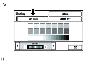
Display the "Display" screen.
-
Turn the light control switch to the tail or head position.
-
Check if "Day Mode" setting on the display adjustment screen is on.
Result Result Proceed to "Day Mode" setting is on A "Day Mode" setting is off B Table 1. Text in Illustration *a Example
- A
TURN "Day Mode" SETTING OFF
- BClick here
-
- Click here
CHECK VEHICLE SIGNAL (OPERATION CHECK)
-
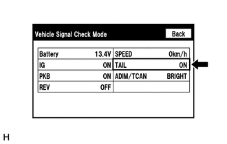
Enter the "Vehicle Signal Check Mode" screen. Refer to Check Vehicle Signal in Operation Check (Click here).
-
Check that the display changes between ON and OFF according to the light control switch operation.
OK Light Control Switch Display Tail or head ON Off OFF Tip:The display is updated once per second. It is normal for the display to lag behind the actual switch operation.
- OK
PROCEED TO NEXT SUSPECTED AREA SHOWN IN PROBLEM SYMPTOMS TABLE (Click here)
- NGClick here
-
- Click here
CHECK HARNESS AND CONNECTOR (ILLUMINATION SIGNAL)
-
Disconnect the H97 multi-media module receiver assembly connector.
-
Measure the resistance according to the value(s) in the table below.
Standard Resistance Tester Connection Condition Specified Condition H97-12 (GND1) - Body ground Always Below 1 Ω -
Measure the voltage according to the value(s) in the table below.
Standard Voltage Tester Connection Condition Specified Condition H97-14 (ILL+) - H97-12 (GND1) Power switch off
Light control switch in tail or head position
11 to 14 V
- OK
PROCEED TO NEXT SUSPECTED AREA SHOWN IN PROBLEM SYMPTOMS TABLE (Click here)
- NG
REPAIR OR REPLACE HARNESS OR CONNECTOR
-