NAVIGATION SYSTEM, Diagnostic DTC:B15C3
| DTC Code | DTC Name |
|---|---|
| B15C3 | Speaker Output Short |
DESCRIPTION
This DTC is stored when a malfunction occurs in the speakers.
| DTC No. | DTC Detection Condition | Trouble Area |
|---|---|---|
| B15C3 | A short is detected in the speaker output circuit. |
|
-
*1: w/ Telematics Transceiver
WIRING DIAGRAM
-
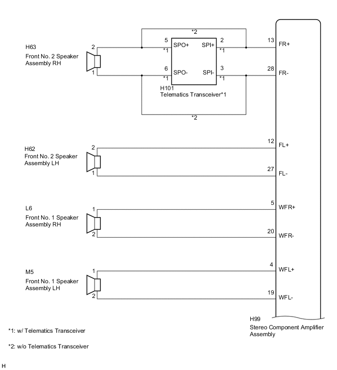
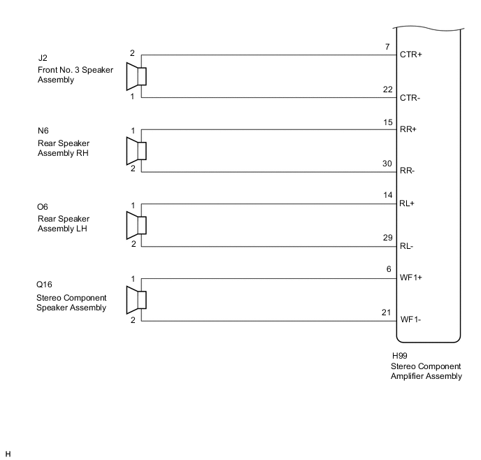
for 8 Speakers
-
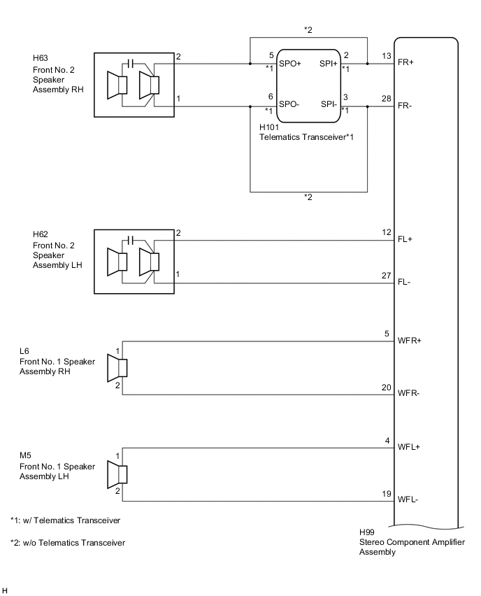
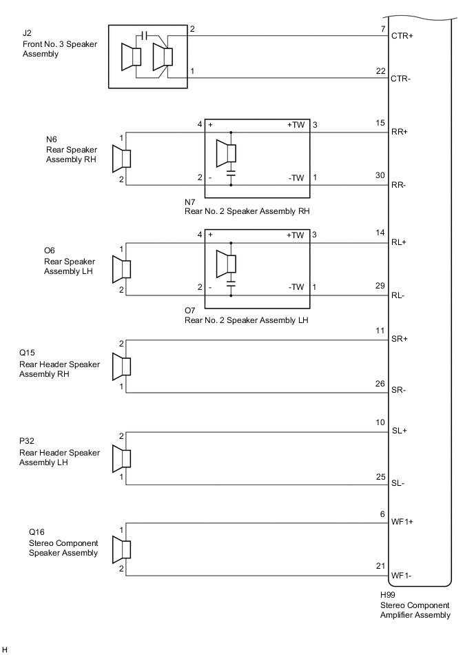
for 15 Speakers
CAUTION / NOTICE / HINT
Note
Depending on the parts that are replaced during vehicle inspection or maintenance, performing initialization, registration or calibration may be needed. Refer to Precautions for Navigation System Click here.
PROCEDURE
-
CONFIRM MODEL
-
Choose the model to be inspected.
Result Model Proceed to for 8 Speakers A for 15 Speakers B
B 
CHECK HARNESS AND CONNECTOR Click here
A 
-
-
CHECK HARNESS AND CONNECTOR
-
Disconnect the H99 stereo component amplifier assembly connector.
-
Disconnect the H63 and H62 front No. 2 speaker assembly connectors.
-
Disconnect the L6 and M5 front No. 1 speaker assembly connectors.
-
Disconnect the J2 front No. 3 speaker assembly connector.
-
Disconnect the O6 and N6 rear speaker assembly connectors.
-
Disconnect the Q16 stereo component speaker assembly connector.
-
Disconnect the H101 telematics transceiver connector (w/ Telematics Transceiver).
-
Measure the resistance between the stereo component amplifier assembly and body ground to check for a short circuit in the wire harness.
Standard Resistance Tester Connection Condition Specified Condition H99-13 (FR+) - Body ground Always 10 kΩ or higher H99-28 (FR-) - Body ground Always 10 kΩ or higher H99-12 (FL+) - Body ground Always 10 kΩ or higher H99-27 (FL-) - Body ground Always 10 kΩ or higher H99-5 (WFR+) - Body ground Always 10 kΩ or higher H99-20 (WFR-) - Body ground Always 10 kΩ or higher H99-4 (WFL+) - Body ground Always 10 kΩ or higher H99-19 (WFL-) - Body ground Always 10 kΩ or higher H99-7 (CTR+) - Body ground Always 10 kΩ or higher H99-22 (CTR-) - Body ground Always 10 kΩ or higher H99-15 (RR+) - Body ground Always 10 kΩ or higher H99-30 (RR-) - Body ground Always 10 kΩ or higher H99-14 (RL+) - Body ground Always 10 kΩ or higher H99-29 (RL-) - Body ground Always 10 kΩ or higher H99-6 (WF1+) - Body ground Always 10 kΩ or higher H99-21 (WF1-) - Body ground Always 10 kΩ or higher -
Measure the resistance between the front No. 2 speaker assembly RH and body ground to check for a short circuit in the wire harness (w/ Telematics Transceiver).
Standard Resistance Tester Connection Condition Specified Condition H63-1 - Body ground Always 10 kΩ or higher H63-2 - Body ground Always 10 kΩ or higher
NG 
REPAIR OR REPLACE HARNESS OR CONNECTOR
OK
-
-
INSPECT FRONT NO. 1 SPEAKER ASSEMBLY
-
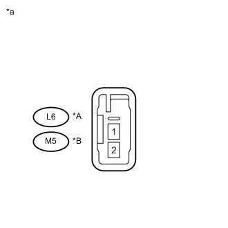
Text in Illustration *A for RH *B for LH *a Component without harness connected
(Front No. 1 Speaker Assembly)
Resistance check
-
Measure the resistance according to the value(s) in the table below.
Standard Resistance Tester Connection Condition Specified Condition L6-1 - L6-2 Always 3.2 to 4.8 Ω M5-1 - M5-2 Always 3.2 to 4.8 Ω
-
NG
REPLACE FRONT NO. 1 SPEAKER ASSEMBLY Click here
OK
-
-
INSPECT FRONT NO. 2 SPEAKER ASSEMBLY
-
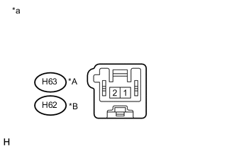
Text in Illustration *A for RH *B for LH *a Component without harness connected
(Front No. 2 Speaker Assembly)
Resistance check
-
Measure the resistance according to the value(s) in the table below.
Standard Resistance Tester Connection Condition Specified Condition H63-1 - H63-2 Always 3.2 to 4.8 Ω H62-1 - H62-2 Always 3.2 to 4.8 Ω
-
NG
REPLACE FRONT NO. 2 SPEAKER ASSEMBLY Click here
OK
-
-
INSPECT FRONT NO. 3 SPEAKER ASSEMBLY
-
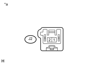
Text in Illustration *a Component without harness connected
(Front No. 3 Speaker Assembly)
Resistance check
-
Measure the resistance according to the value(s) in the table below.
Standard Resistance Tester Connection Condition Specified Condition J2-1 - J2-2 Always 4.0 to 6.0 Ω
-
NG
REPLACE FRONT NO. 3 SPEAKER ASSEMBLY Click here
OK
-
-
INSPECT REAR SPEAKER ASSEMBLY
-
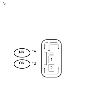
Text in Illustration *A for RH *B for LH *a Component without harness connected
(Rear Speaker Assembly)
Resistance check
-
Measure the resistance according to the value(s) in the table below.
Standard Resistance Tester Connection Condition Specified Condition N6-1 - N6-2 Always 3.2 to 4.8 Ω O6-1 - O6-2 Always 3.2 to 4.8 Ω
-
NG
REPLACE REAR SPEAKER ASSEMBLY Click here
OK
-
-
INSPECT STEREO COMPONENT SPEAKER ASSEMBLY
-
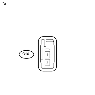
Text in Illustration *a Component without harness connected
(Stereo Component Speaker Assembly)
Resistance check
-
Measure the resistance according to the value(s) in the table below.
Standard Resistance Tester Connection Condition Specified Condition Q16-1 - Q16-2 Always 2.0 to 3.0 Ω
-
-
Proceed to the next step based on the inspection result.
Result Result Proceed to OK (w/o Telematics Transceiver) A OK (w/ Telematics Transceiver) B NG C
A
REPLACE STEREO COMPONENT AMPLIFIER ASSEMBLY Click here
B
INSPECT TELEMATICS TRANSCEIVER Click here
C
REPLACE STEREO COMPONENT SPEAKER ASSEMBLY Click here
-
-
CHECK HARNESS AND CONNECTOR
-
Disconnect the H99 stereo component amplifier assembly connector.
-
Disconnect the H101 telematics transceiver connector (w/ Telematics Transceiver).
-
Disconnect the H63 and H62 front No. 2 speaker assembly connectors.
-
Disconnect the L6 and M5 front No. 1 speaker assembly connectors.
-
Disconnect the J2 front No. 3 speaker assembly connector.
-
Disconnect the N6 and O6 rear speaker assembly connectors.
-
Disconnect the N7 and O7 rear No. 2 speaker assembly connectors.
-
Disconnect the Q15 and P32 rear header speaker assembly connectors.
-
Disconnect the Q16 stereo component speaker assembly connector.
-
Measure the resistance between the stereo component amplifier assembly and body ground to check for a short circuit in the wire harness.
Standard Resistance Tester Connection Condition Specified Condition H99-13 (FR+) - Body ground Always 10 kΩ or higher H99-28 (FR-) - Body ground Always 10 kΩ or higher H99-12 (FL+) - Body ground Always 10 kΩ or higher H99-27 (FL-) - Body ground Always 10 kΩ or higher H99-5 (WFR+) - Body ground Always 10 kΩ or higher H99-20 (WFR-) - Body ground Always 10 kΩ or higher H99-4 (WFL+) - Body ground Always 10 kΩ or higher H99-19 (WFL-) - Body ground Always 10 kΩ or higher H99-7 (CTR+) - Body ground Always 10 kΩ or higher H99-22 (CTR-) - Body ground Always 10 kΩ or higher H99-15 (RR+) - Body ground Always 10 kΩ or higher H99-30 (RR-) - Body ground Always 10 kΩ or higher H99-14 (RL+) - Body ground Always 10 kΩ or higher H99-29 (RL-) - Body ground Always 10 kΩ or higher H99-11 (SR+) - Body ground Always 10 kΩ or higher H99-26 (SR-) - Body ground Always 10 kΩ or higher H99-10 (SL+) - Body ground Always 10 kΩ or higher H99-25 (SL-) - Body ground Always 10 kΩ or higher H99-6 (WF1+) - Body ground Always 10 kΩ or higher H99-21 (WF1-) - Body ground Always 10 kΩ or higher -
Measure the resistance between the front No. 2 speaker assembly RH and body ground to check for a short circuit in the wire harness (w/ Telematics Transceiver).
Standard Resistance Tester Connection Condition Specified Condition H63-1 - Body ground Always 10 kΩ or higher H63-2 - Body ground Always 10 kΩ or higher -
Measure the resistance between each of the rear No. 2 speaker assemblies and body ground to check for a short circuit in the wire harness.
Standard Resistance Tester Connection Condition Specified Condition N7-4 (+) - Body ground Always 10 kΩ or higher N7-2 (-) - Body ground Always 10 kΩ or higher O7-4 (+) - Body ground Always 10 kΩ or higher O7-2 (-) - Body ground Always 10 kΩ or higher
NG
REPAIR OR REPLACE HARNESS OR CONNECTOR
OK
-
-
INSPECT FRONT NO. 1 SPEAKER ASSEMBLY
-

Text in Illustration *A for RH *B for LH *a Component without harness connected
(Front No. 1 Speaker Assembly)
Resistance check
-
Measure the resistance according to the value(s) in the table below.
Standard Resistance Tester Connection Condition Specified Condition L6-1 - L6-2 Always 4.2 to 6.2 Ω M5-1 - M5-2 Always 4.2 to 6.2 Ω
-
NG
REPLACE FRONT NO. 1 SPEAKER ASSEMBLY Click here
OK
-
-
REPLACE FRONT NO. 2 SPEAKER ASSEMBLY
-
Replace the front No. 2 speaker assembly Click here.
-
Clear the DTCs Click here.
-
Recheck for DTCs and check that no DTCs are output.
OK No DTCs are output. Tech Tips
-
Connect all the connectors to the front No. 2 speaker assemblies that were disconnected.
-
When there is a possibility that either the right or left front speaker is defective, inspect by interchanging the right one with the left one.
-
Perform the above inspection on both LH and RH sides.
-
OK
END (FRONT NO. 2 SPEAKER ASSEMBLY WAS DEFECTIVE)
NG
-
-
REPLACE FRONT NO. 3 SPEAKER ASSEMBLY
-
Replace the front No. 3 speaker assembly Click here.
-
Clear the DTCs Click here.
-
Recheck for DTCs and check that no DTCs are output.
OK No DTCs are output. Tech Tips
Connect all the connectors to the front No. 3 speaker assembly that were disconnected.
OK
END (FRONT NO. 3 SPEAKER ASSEMBLY WAS DEFECTIVE)
NG
-
-
INSPECT REAR SPEAKER ASSEMBLY
-
Text in Illustration *A for RH *B for LH *a Component without harness connected
(Rear Speaker Assembly)
Resistance check
-
Measure the resistance according to the value(s) in the table below.
Standard Resistance Tester Connection Condition Specified Condition N6-1 - N6-2 Always 3.6 to 5.6 Ω O6-1 - O6-2 Always 3.6 to 5.6 Ω
-
NG
REPLACE REAR SPEAKER ASSEMBLY Click here
OK
-
-
INSPECT REAR NO. 2 SPEAKER ASSEMBLY
-
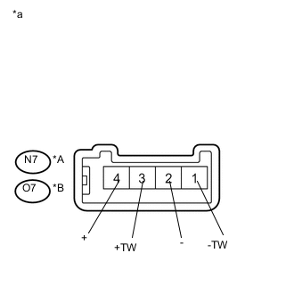
Text in Illustration *A for RH *B for LH *a Component without harness connected
(Rear No. 2 Speaker Assembly)
Resistance check
-
Measure the resistance according to the value(s) in the table below.
Standard Resistance Tester Connection Condition Specified Condition N7-3 (+TW) - N7-1 (-TW) Always 10 kΩ or higher N7-3 (+TW) - N7-4 (+) Always Below 1 Ω N7-1 (-TW) - N7-2 (-) Always Below 1 Ω O7-3 (+TW) - O7-1 (-TW) Always 10 kΩ or higher O7-3 (+TW) - O7-4 (+) Always Below 1 Ω O7-1 (-TW) - O7-2 (-) Always Below 1 Ω
-
NG
REPLACE REAR NO. 2 SPEAKER ASSEMBLY Click here
OK
-
-
REPLACE REAR NO. 2 SPEAKER ASSEMBLY
-
Replace the rear No. 2 speaker assembly Click here.
-
Clear the DTCs Click here.
-
Recheck for DTCs and check that no DTCs are output.
OK No DTCs are output. Tech Tips
-
Connect all the connectors to the rear No. 2 speaker assemblies that were disconnected.
-
When there is a possibility that either the right or left front speaker is defective, inspect by interchanging the right one with the left one.
-
Perform the above inspection on both LH and RH sides.
-
OK
END (REAR NO. 2 SPEAKER ASSEMBLY WAS DEFECTIVE)
NG
-
-
INSPECT REAR HEADER SPEAKER ASSEMBLY
-
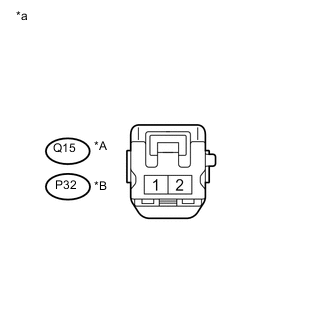
Text in Illustration *A for RH *B for LH *a Component without harness connected
(Rear Header Speaker Assembly)
Resistance check
-
Measure the resistance according to the value(s) in the table below.
Standard Resistance Tester Connection Condition Specified Condition Q15-1 - Q15-2 Always 7.0 to 10.6 Ω P32-1 - P32-2 Always 7.0 to 10.6 Ω
-
NG
REPLACE REAR HEADER SPEAKER ASSEMBLY Click here
OK
-
-
INSPECT STEREO COMPONENT SPEAKER ASSEMBLY
-
Text in Illustration *a Component without harness connected
(Stereo Component Speaker Assembly)
Resistance check
-
Measure the resistance according to the value(s) in the table below.
Standard Resistance Tester Connection Condition Specified Condition Q16-1 - Q16-2 Always 5.0 to 7.0 Ω
-
-
Proceed to the next step based on the inspection result.
Result Result Proceed to OK (w/ Telematics Transceiver) A OK (w/o Telematics Transceiver) B NG C
B
REPLACE STEREO COMPONENT AMPLIFIER ASSEMBLY Click here
C
REPLACE STEREO COMPONENT SPEAKER ASSEMBLY Click here
A
-
-
INSPECT TELEMATICS TRANSCEIVER
-
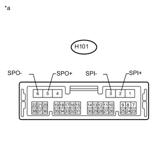
Text in Illustration *a Component without harness connected
(Telematics Transceiver)
Resistance check
-
Measure the resistance according to the value(s) in the table below.
Standard Resistance Tester Connection Condition Specified Condition H101-2 (SPI+) - H101-5 (SPO+) Always Below 1 Ω H101-3 (SPI-) - H101-6 (SPO-) Always Below 1 Ω H101-2 (SPI+) - H101-3 (SPI-) Always 10 kΩ or higher H101-5 (SPO+) - H101-6 (SPO-) Always 10 kΩ or higher H101-2 (SPI+) - Body ground Always 10 kΩ or higher H101-3 (SPI-) - Body ground Always 10 kΩ or higher
-
OK
REPLACE STEREO COMPONENT AMPLIFIER ASSEMBLY Click here
NG
REPLACE TELEMATICS TRANSCEIVER Click here
-