AUDIO AND VISUAL SYSTEM(w/o Multi-display) Radio Receiver Communication Error
PROCEDURE
-
IDENTIFY COMPONENT SHOWN BY SUB-CODE
-
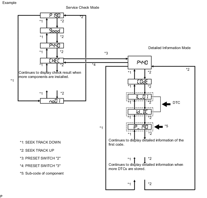
Enter diagnostic mode Click here.
-
Press preset switch "2" to change the mode to "Detailed Information Mode".
-
Identify the component shown by the sub-code.
Tech Tips
-
The sub-code "P190" shown in the above example indicates the radio receiver assembly.
-
For details of the DTC display, refer to DTC Check/Clear Click here.
-
NEXT 
-
-
CHECK COMPONENT SHOWN BY SUB-CODE
-
Select the component shown by the sub-code.
Component Table Component Proceed to Except radio receiver assembly A Radio receiver assembly (190) B
B 
REPLACE RADIO RECEIVER ASSEMBLY Click here
A
-
-
CHECK POWER SOURCE CIRCUIT OF COMPONENT SHOWN BY SUB-CODE
-
Inspect the power source circuit of the component shown by the sub-code.
If the power source circuit is operating normally, proceed to the next step.
Component Table Component Proceed to Stereo component amplifier assembly (440) Stereo component amplifier power source circuit Click here
Accessory meter assembly (1D4) Accessory meter does not illuminate Click here
Air conditioning control panel (1C4) Air conditioning control panel circuit Click here
NEXT
-
-
INSPECT RADIO RECEIVER ASSEMBLY
-
Disconnect the H82, H85 and H83 radio receiver assembly connectors.
-
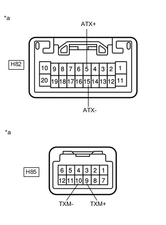
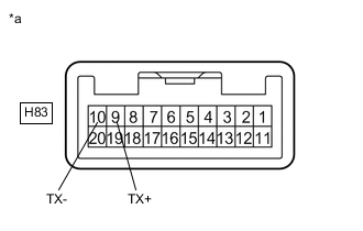
Measure the resistance according to the value(s) in the table below.
Standard Resistance Tester Connection Condition Specified Condition H82-5 (ATX+) - H82-15 (ATX-) Always 60 to 80 Ω H85-9 (TXM+) - H85-10 (TXM-) Always 60 to 80 Ω H83-9 (TX+) - H83-10 (TX-) Always 60 to 80 Ω Text in Illustration *a Component without harness connected
(Radio Receiver Assembly)
NG
REPLACE RADIO RECEIVER ASSEMBLY Click here
OK
-
-
CHECK HARNESS AND CONNECTOR (RADIO RECEIVER ASSEMBLY - COMPONENT SHOWN BY SUB-CODE)
Tech Tips
-
Start the check from the circuit that is near the component shown by the sub-code first.
-
For details of the connectors, refer to Terminals of ECU Click here.
-
Referring to the following AVC-LAN wiring diagram, check the AVC-LAN circuit between the radio receiver assembly and component shown by the sub-code.
-
Disconnect all connectors between the radio receiver assembly and component shown by the sub-code.
-
Check for an open or short in the AVC-LAN circuit between the radio receiver assembly and component shown by the sub-code.
OK There is no open or short circuit. 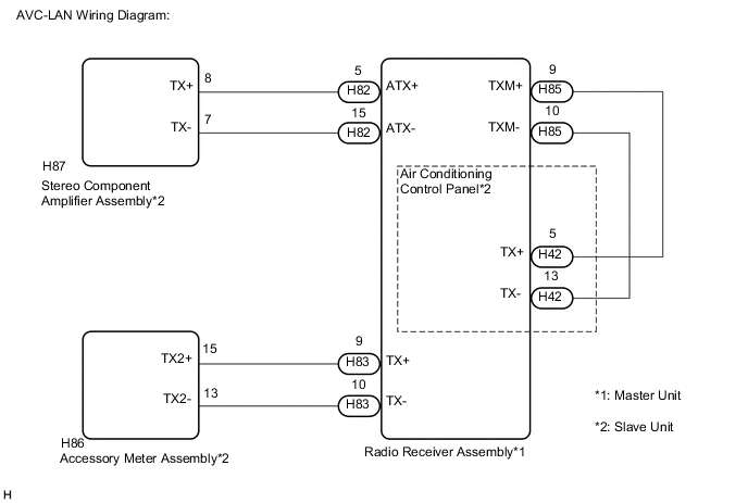
-
NG
REPAIR OR REPLACE HARNESS OR CONNECTOR
OK
-
-
REPLACE COMPONENT SHOWN BY SUB-CODE
-
Replace the component shown by the sub-code with a known good one and check if the same problem occurs again.
OK Malfunction disappears.
OK
END
NG
REPLACE RADIO RECEIVER ASSEMBLY Click here
-