AUDIO AND VISUAL SYSTEM(w/o Multi-display) AVC-LAN Circuit
DESCRIPTION
Each audio system component connected to the AVC-LAN (communication bus) transfers switch signals via the audio visual communication local area network.
If a short to +B or short to ground occurs in the AVC-LAN, the audio system will not function normally as communication is stopped.
PROCEDURE
-
INSPECT RADIO RECEIVER ASSEMBLY
-
Disconnect the H82, H85 and H83 radio receiver assembly connectors.
-
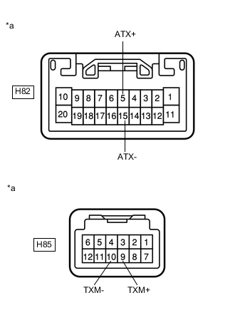
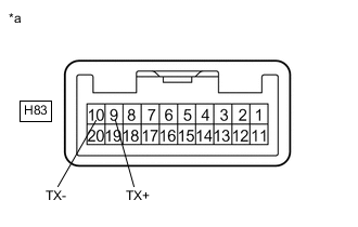
Measure the resistance according to the value(s) in the table below.
Standard Resistance Tester Connection Condition Specified Condition H82-5 (ATX+) - H82-15 (ATX-) Always 60 to 80 Ω H85-9 (TXM+) - H85-10 (TXM-) Always 60 to 80 Ω H83-9 (TX+) - H83-10 (TX-) Always 60 to 80 Ω Text in Illustration *a Component without harness connected
(Radio Receiver Assembly)
NG 
REPLACE RADIO RECEIVER ASSEMBLY Click here
OK 
-
-
CHECK HARNESS AND CONNECTOR (RADIO RECEIVER ASSEMBLY - EACH COMPONENT)
Tech Tips
For details of the connectors, refer to Terminals of ECU Click here.
-
Referring to the following AVC-LAN wiring diagram, check all AVC-LAN circuits.
-
Disconnect all connectors in all AVC-LAN circuits.
-
Check for an open or short in all AVC-LAN circuits.
OK There is no open or short circuit. 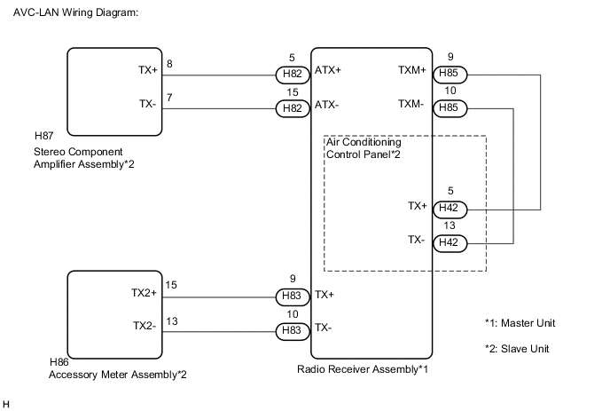
-
NG
REPAIR OR REPLACE HARNESS OR CONNECTOR
OK
-
-
INSPECT MALFUNCTIONING PARTS
-
Disconnect and reconnect each slave unit one by one until the master unit returns to normal operation.
Tech Tips
-
Check all slave units.
-
When disconnecting a slave unit causes the master unit to return to normal operation, this indicates that the slave unit is malfunctioning. Replace the malfunctioning slave unit.
OK Master unit returns to normal operation. -
OK
REPLACE MALFUNCTIONING PARTS
NG
PROCEED TO NEXT SUSPECTED AREA SHOWN IN PROBLEM SYMPTOMS TABLE Click here
-