AUDIO AND VISUAL SYSTEM(w/o Multi-display), Diagnostic DTC:74-40
| DTC Code | DTC Name |
|---|---|
| 74-40 | Short in Speaker Circuit |
DESCRIPTION
This DTC is stored when a malfunction occurs in the speakers.
| DTC No. | DTC Detection Condition | Trouble Area |
|---|---|---|
| 74-40 | A short is detected in the speaker output circuit. |
|
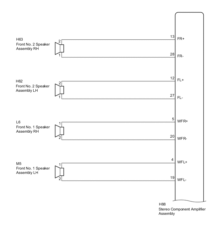
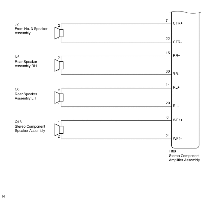
WIRING DIAGRAM
PROCEDURE
-
CHECK HARNESS AND CONNECTOR
-
Disconnect the H88 stereo component amplifier assembly connector.
-
Disconnect the L6 and M5 front No. 1 speaker assembly connectors.
-
Disconnect the H63 and H62 front No. 2 speaker assembly connectors.
-
Disconnect the O6 and N6 rear speaker assembly connectors.
-
Disconnect the J2 front No. 3 speaker assembly connector.
-
Disconnect the Q16 stereo component speaker assembly connector.
-
Measure the resistance between the stereo component amplifier assembly and body ground to check for a short circuit in the wire harness.
Standard Resistance Tester Connection Condition Specified Condition H88-13 (FR+) - Body ground Always 10 kΩ or higher H88-28 (FR-) - Body ground Always 10 kΩ or higher H88-12 (FL+) - Body ground Always 10 kΩ or higher H88-27 (FL-) - Body ground Always 10 kΩ or higher H88-5 (WFR+) - Body ground Always 10 kΩ or higher H88-20 (WFR-) - Body ground Always 10 kΩ or higher H88-4 (WFL+) - Body ground Always 10 kΩ or higher H88-19 (WFL-) - Body ground Always 10 kΩ or higher H88-7 (CTR+) - Body ground Always 10 kΩ or higher H88-22 (CTR-) - Body ground Always 10 kΩ or higher H88-15 (RR+) - Body ground Always 10 kΩ or higher H88-30 (RR-) - Body ground Always 10 kΩ or higher H88-14 (RL+) - Body ground Always 10 kΩ or higher H88-29 (RL-) - Body ground Always 10 kΩ or higher H88-6 (WF1+) - Body ground Always 10 kΩ or higher H88-21 (WF1-) - Body ground Always 10 kΩ or higher
NG 
REPAIR OR REPLACE HARNESS OR CONNECTOR
OK 
-
-
INSPECT FRONT NO. 1 SPEAKER ASSEMBLY
-
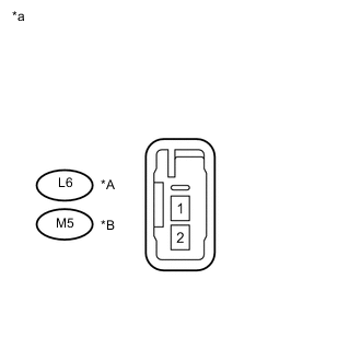
Text in Illustration *A for RH *B for LH *a Component without harness connected
(Front No. 1 Speaker Assembly)
Resistance check
-
Measure the resistance according to the value(s) in the table below.
Standard Resistance Tester Connection Condition Specified Condition L6-1 - L6-2 Always 3.2 to 4.8 Ω M5-1 - M5-2 Always 3.2 to 4.8 Ω
-
NG
REPLACE FRONT NO. 1 SPEAKER ASSEMBLY Click here
OK
-
-
INSPECT FRONT NO. 2 SPEAKER ASSEMBLY
-
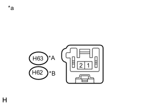
Text in Illustration *A for RH *B for LH *a Component without harness connected
(Front No. 2 Speaker Assembly)
Resistance check
-
Measure the resistance according to the value(s) in the table below.
Standard Resistance Tester Connection Condition Specified Condition H63-1 - H63-2 Always 3.2 to 4.8 Ω H62-1 - H62-2 Always 3.2 to 4.8 Ω
-
NG
REPLACE FRONT NO. 2 SPEAKER ASSEMBLY Click here
OK
-
-
INSPECT FRONT NO. 3 SPEAKER ASSEMBLY
-
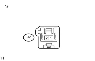
Text in Illustration *a Component without harness connected
(Front No. 3 Speaker Assembly)
Resistance check
-
Measure the resistance according to the value(s) in the table below.
Standard Resistance Tester Connection Condition Specified Condition J2-1 - J2-2 Always 4.0 to 6.0 Ω
-
NG
REPLACE FRONT NO. 3 SPEAKER ASSEMBLY Click here
OK
-
-
INSPECT REAR SPEAKER ASSEMBLY
-
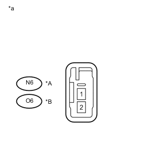
Text in Illustration *A for RH *B for LH *a Component without harness connected
(Rear Speaker Assembly)
Resistance check
-
Measure the resistance according to the value(s) in the table below.
Standard Resistance Tester Connection Condition Specified Condition N6-1 - N6-2 Always 3.2 to 4.8 Ω O6-1 - O6-2 Always 3.2 to 4.8 Ω
-
NG
REPLACE REAR SPEAKER ASSEMBLY Click here
OK
-
-
INSPECT STEREO COMPONENT SPEAKER ASSEMBLY
-
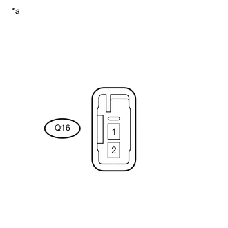
Text in Illustration *a Component without harness connected
(Stereo Component Speaker Assembly)
Resistance check
-
Measure the resistance according to the value(s) in the table below.
Standard Resistance Tester Connection Condition Specified Condition Q16-1 - Q16-2 Always 2.0 to 3.0 Ω
-
OK
REPLACE STEREO COMPONENT AMPLIFIER ASSEMBLY Click here
NG
REPLACE STEREO COMPONENT SPEAKER ASSEMBLY Click here
-