AUDIO AND VISUAL SYSTEM(w/ Multi-display), Diagnostic DTC:B1321, B1323, B1563
| DTC Code | DTC Name |
|---|---|
| B1321 | Lost Communication with EMV |
| B1323 | Lost Communication with Haptic Device |
| B1563 | Haptic Device Disconnected |
DESCRIPTION
These DTCs are stored when communication between the multi-media module receiver assembly and the remote touch is not possible.
| DTC No. | DTC Detection Condition | Trouble Area |
|---|---|---|
| B1321 | The multi-media module receiver assembly cannot receive data from the remote touch. |
|
| B1323 | The remote touch cannot receive data from the multi-media module receiver assembly. | |
| B1563 | The remote touch is/was not connected while the power switch is/was on (ACC or IG). |
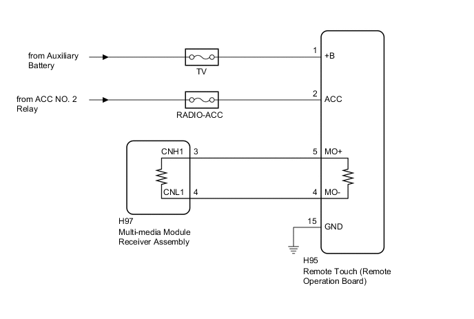
WIRING DIAGRAM
CAUTION / NOTICE / HINT
Note
-
Depending on the parts that are replaced during vehicle inspection or maintenance, performing initialization, registration or calibration may be needed. Refer to Precaution for Audio and Visual System Click here.
-
Inspect the fuses for circuits related to this system before performing the following inspection procedure.
PROCEDURE
-
CHECK HARNESS AND CONNECTOR (MULTI-MEDIA MODULE RECEIVER ASSEMBLY - REMOTE TOUCH (REMOTE OPERATION BOARD))
-
Disconnect the H97 multi-media module receiver assembly connector.
-
Disconnect the H95 remote touch (remote operation board) connector.
-
Measure the resistance according to the value(s) in the table below.
Standard Resistance Tester Connection Condition Specified Condition H97-3 (CNH1) - H95-5 (MO+) Always Below 1 Ω H97-4 (CNL1) - H95-4 (MO-) Always Below 1 Ω H97-3 (CNH1) - Body ground Always 10 kΩ or higher H97-4 (CNL1) - Body ground Always 10 kΩ or higher
NG 
REPAIR OR REPLACE HARNESS OR CONNECTOR
OK 
-
-
CHECK HARNESS AND CONNECTOR (REMOTE TOUCH (REMOTE OPERATION BOARD) POWER SOURCE)
-
Disconnect the H95 remote touch (remote operation board) connector.
-
Measure the voltage according to the value(s) in the table below.
Standard Voltage Tester Connection Condition Specified Condition H95-1 (+B) - Body ground Power switch off 11 to 14 V H95-2 (ACC) - Body ground Power switch on (ACC) 11 to 14 V -
Measure the resistance according to the value(s) in the table below.
Standard Resistance Tester Connection Condition Specified Condition H95-15 (GND) - Body ground Always Below 1 Ω
NG
REPAIR OR REPLACE HARNESS OR CONNECTOR
OK
-
-
REMOTE TOUCH SELF CHECK (REMOTE TOUCH SWITCH KNOB FEEDBACK FORCE GENERATION CHECK)
-
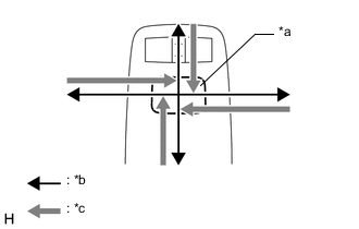
Text in Illustration *a Switch Knob *b Control Direction *c Feedback Force Check the remote touch switch knob feedback force.
-
Move the remote touch switch knob up, down, right and left to check that feedback force is generated.
OK Feedback force is generated. Tech Tips
When the power switch is turned on (ACC), feedback force is generated. When the power switch is turned off, feedback force is not generated, and the remote touch switch knob will move freely.
-
NG
REPLACE REMOTE OPERATION BOARD Click here
OK
-
-
REPLACE MULTI-MEDIA MODULE RECEIVER ASSEMBLY
-
Replace the multi-media module receiver assembly Click here.
-
Check if the same malfunction recurs.
Result Result Proceed to Malfunction does not recur
(returns to normal)
A Malfunction recurs B
A
END
B
REPLACE REMOTE OPERATION BOARD Click here
-