CAUTION / NOTICE / HINT
-
Do not drop the power steering ECU with motor assembly, strike it with tools or subject it to impacts.
-
If the power steering ECU with motor assembly is subjected to an impact, replace it with a new one.
-
Do not pull the wire harness of the electric power steering column sub-assembly.
-
Do not allow any moisture to come into contact with the power steering ECU with motor assembly.
-
Do not loosen any bolts not mentioned in the procedure.
PROCEDURE
- Click here
INSTALL POWER STEERING ECU WITH MOTOR ASSEMBLY
-
Install a new electric power steering motor shaft damper to the electric power steering column sub-assembly.
-
Install a new electric power steering motor shaft spacer to the electric power steering column sub-assembly.
-
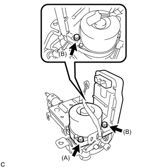
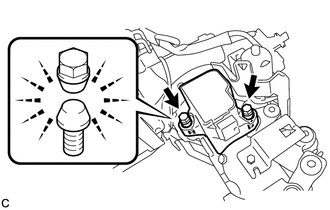
Temporarily install the power steering ECU with motor assembly to the electric power steering column sub-assembly with 3 bolts.
Note:
-
Bolt (A) is shorter than bolt (B). Make sure to install them to the correct positions.
-
When temporarily installing the 3 bolts to the power steering ECU with motor assembly, do not tighten them all the way down.
-
-
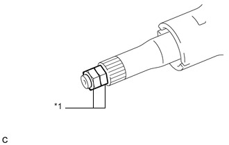
Install the 2 service nuts to the steering main shaft.
Table 1. Text in Illustration *1 Service Nut Recommended service nut Thread diameter 12.0 mm (0.472 in.) Thread pitch 1.25 mm (0.0492 in.) -
Simultaneously rotate the service nut that was installed first counterclockwise and rotate the service nut that was installed second clockwise to lock them.
Note:Do not apply excess torque to the service nuts by using a tool such as an impact wrench.
Tip:These nuts are installed to turn the steering main shaft. They should be removed after inspecting the steering main shaft rotating torque.
-
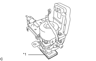
Securely set the steering column assembly on a wooden block or similar item.
Table 2. Text in Illustration *1 Wooden Block Note:
-
Be sure to hold the steering column assembly by hand so that it will not move while servicing.
-
Make sure that the power steering motor assembly is facing upward.
-
-
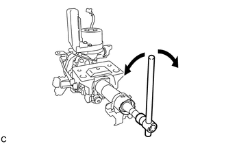
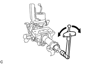
Turn the steering main shaft once 180 degrees to the left and then 180 degrees to the right at a speed of 60 rpm, and repeat 2 to 3 times to adjust the axis of the power steering ECU with motor assembly.
-
Tighten the 3 bolts.
19 N*m 189 kgf*cm 14 ft.*lbf Note:Make sure not to move the power steering motor assembly after adjusting the axis.
-
Measure the turning torque of the steering main shaft.
Turning torque 1.1 N*m 1.9 N*m 12 kgf*cm 19 kgf*cm 10 in.*lbf 17 in.*lbf Note:Ensure that there is no abnormal resistance during rotation.
If the torque is not as specified, readjust the axis of the power steering ECU with motor assembly.
-
Remove the 2 service nuts from the steering main shaft.
-
Connect the connector to the power steering ECU with motor assembly.
-
- Click here
INSTALL ECU WIRE SUB-ASSEMBLY
-
Engage the 2 wire harness clamps to install the ECU wire sub-assembly.
-
Connect the 2 connectors to the power steering ECU with motor assembly.
-
- Click here
INSTALL POWER STEERING ECU PROTECTOR
-
Install a new power steering ECU protector to the power steering ECU with motor assembly.
-
- Click here
INSTALL MULTIPLEX TILT AND TELESCOPIC ECU
-
Engage the claw to install the multiplex tilt and telescopic ECU to the electric power steering column sub-assembly.
-
- Click here
INSTALL STEERING LOCK ACTUATOR ASSEMBLY
Tip:When replacing the steering lock actuator assembly, refer to Service Bulletin.
-
Temporarily install the steering lock actuator assembly to the steering column assembly with 2 new tapered-head bolts.
-
Tighten the 2 tapered-head bolts until the bolt heads break off.
-