PROCEDURE
- Click here
PRECAUTION
- Click here
DISCONNECT CABLE FROM NEGATIVE AUXILIARY BATTERY TERMINAL (for Power Tilt and Power Telescopic Steering Column)
-
Disable the auto tilt away function by changing the customize parameter (Click here).
Note:Record the current customize parameter setting (whether the auto tilt away function is enabled or disabled) in order to restore the current setting after finishing this operation.
Tip:Performing the above operation disables the auto tilt away function when the power switch is turned off.
-
Turn the power switch on (IG). Operate the tilt and telescopic switch to fully extend and lower the steering column assembly.
-
Turn the power switch off and disconnect the cable from the negative (-) auxiliary battery terminal (Click here).
CAUTION:Wait at least 90 seconds after disconnecting the cable from the negative (-) auxiliary battery terminal to disable the SRS system.
Note:When disconnecting the cable, some systems need to be initialized after the cable is reconnected (Click here).
-
- Click here
TURN FRONT WHEELS TO FACE STRAIGHT AHEAD
- Click here
REMOVE FRONT WHEEL
- Click here
REMOVE HORN BUTTON ASSEMBLY
- Click here
REMOVE STEERING WHEEL ASSEMBLY
- Click here
REMOVE LOWER NO. 1 INSTRUMENT PANEL AIRBAG ASSEMBLY
- Click here
REMOVE LOWER STEERING COLUMN COVER (for Manual Tilt and Manual Telescopic Steering Column)
-
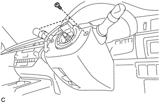
Remove the 2 screws.
-
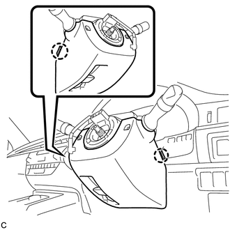
Push the right and left sides of the lower steering column cover, and disengage the 2 claws.
-
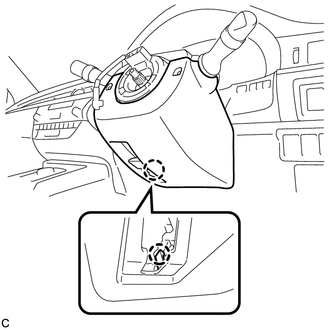
Insert a finger into the opening of the tilt lever of the lower steering column cover to disengage the claw and remove the lower steering column cover.
-
- Click here
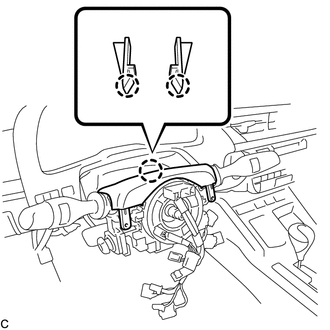
REMOVE LOWER STEERING COLUMN COVER (for Power Tilt and Power Telescopic Steering Column)
-
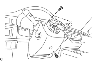
Remove the 3 screws.
-
Push the right and left sides of the lower steering column cover, and disengage the 2 claws to remove the lower steering column cover.
Note:Do not damage the tilt and telescopic switch.
-
- Click here
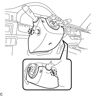
REMOVE UPPER STEERING COLUMN COVER
-

Disengage the 4 clips and 2 guides from the upper steering column cover.
-
Disengage the 2 claws to remove the upper steering column cover.
-
- Click here
REMOVE TURN SIGNAL SWITCH ASSEMBLY WITH SPIRAL CABLE SUB-ASSEMBLY
Note:
-
Do not replace the spiral cable with sensor sub-assembly with the auxiliary battery connected and the power switch on (IG).
-
Do not rotate the spiral cable with sensor sub-assembly without the steering wheel with the auxiliary battery connected and the power switch on (IG).
-
Ensure that the steering wheel is installed and aligned straight when inspecting the steering sensor.
-
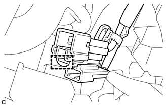
Disconnect the connectors from the turn signal switch assembly with spiral cable sub-assembly.
-
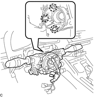
Disengage the 3 claws to remove the turn signal switch assembly with spiral cable sub-assembly from the steering post assembly.
-
- Click here
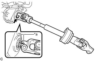
SEPARATE STEERING INTERMEDIATE SHAFT ASSEMBLY
-
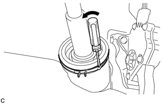
Using a screwdriver, loosen the clamp as shown in the illustration.
-
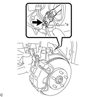
Put matchmarks on the steering intermediate shaft assembly and the steering link assembly.
Table 1. Text in Illustration *a Matchmark -
Remove the bolt and separate the steering intermediate shaft assembly from the steering link assembly.
-
- Click here
REMOVE NO. 2 AIR DUCT SUB-ASSEMBLY (for LHD)
-
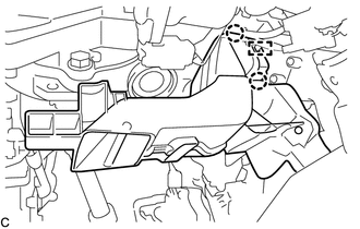
Disengage the 2 claws and guide to remove the No. 2 air duct sub-assembly.
-
- Click here
REMOVE NO. 2 AIR DUCT SUB-ASSEMBLY (for RHD)
-
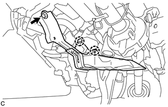
Remove the bolt.
-
Disengage the 2 claws to remove the No. 2 air duct sub-assembly.
-
- Click here
REMOVE STEERING POST ASSEMBLY (for Manual Tilt and Manual Telescopic Steering Column)
-
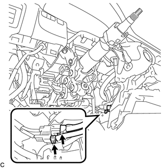
Disconnect the connectors and disengage the wire harness clamps from the steering post assembly.
-
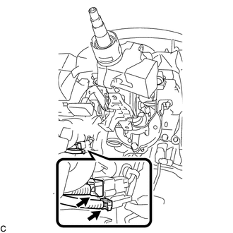
Disconnect the 2 connectors.
-
Disengage the clamp.
-
Remove the bolt to separate the ground wire.
-
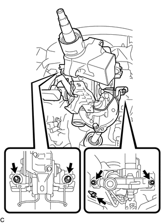
Remove the 4 nuts and the steering post assembly.
-
- Click here
REMOVE STEERING POST ASSEMBLY (for Power Tilt and Power Telescopic Steering Column)
-
Disconnect the connectors and disengage the wire harness clamps from the steering post assembly.
-
Disconnect the 2 connectors.
-
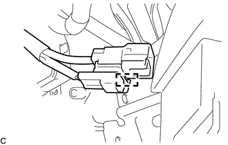
Disengage the clamp.
-

Remove the bolt to separate the ground wire.
-
Remove the 4 nuts and the steering post assembly.
-
- Click here
REMOVE STEERING INTERMEDIATE SHAFT ASSEMBLY
-
Remove the bolt and slide the steering intermediate shaft assembly.
Table 2. Text in Illustration *a Matchmark Note:Do not separate the steering intermediate shaft assembly from the steering column assembly.
-
Put matchmarks on the steering intermediate shaft assembly and the steering post assembly.
-
Remove the steering intermediate shaft assembly from the steering column assembly.
-