POWER STEERING SYSTEM Drive Mode Switch Circuit
DESCRIPTION
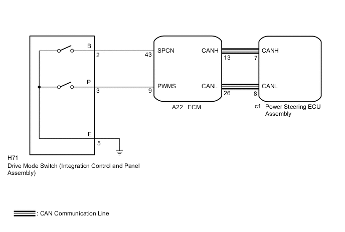
The EPS characteristics change according to operation of the drive mode switch (integration control and panel assembly).
WIRING DIAGRAM
PROCEDURE
-
CHECK CAN COMMUNICATION SYSTEM
-
Check for DTCs (See page for with Central Gateway ECU, Click here for without Central Gateway ECU).
Result Result Proceed to DTCs are not output. A DTCs are output (w/ Central Gateway ECU). B DTCs are output (w/o Central Gateway ECU). C
B 
GO TO CAN COMMUNICATION SYSTEM (w/ Central Gateway ECU) Click here
C
GO TO CAN COMMUNICATION SYSTEM (w/o Central Gateway ECU) Click here
A 
-
-
CHECK HARNESS AND CONNECTOR (DRIVE MODE SWITCH (INTEGRATION CONTROL AND PANEL ASSEMBLY) - BODY GROUND)
-
Turn the power switch off.
-
Disconnect the H71 drive mode switch (integration control and panel assembly) connector.
-
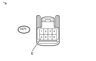
Text in Illustration *a Front view of wire harness connector
(to Drive Mode Switch (Integration Control and Panel Assembly))
Measure the resistance according to the value(s) in the table below.
Standard Resistance Tester Connection Specified Condition H71-5 (E) - Body ground Below 1 Ω
NG
REPAIR OR REPLACE HARNESS OR CONNECTOR
OK
-
-
INSPECT DRIVE MODE SWITCH (INTEGRATION CONTROL AND PANEL ASSEMBLY)
-
Inspect drive mode switch (integration control and panel assembly) Click here.
OK Drive mode switch (integration control and panel assembly) is normal.
NG
REPLACE DRIVE MODE SWITCH (INTEGRATION CONTROL AND PANEL ASSEMBLY) Click here
OK
-
-
CHECK HARNESS AND CONNECTOR (DRIVE MODE SWITCH (INTEGRATION CONTROL AND PANEL ASSEMBLY) - ECM)
-
Reconnect the H71 drive mode switch (integration control and panel assembly) connector.
-
Disconnect the A22 ECM connector.
-
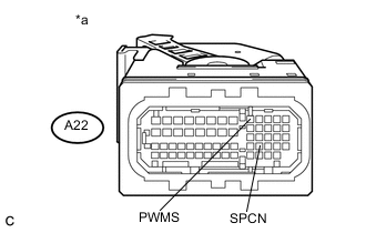
Text in Illustration *a Front view of wire harness connector
(to ECM)
Measure the resistance according to the value(s) in the table below.
Standard Resistance Tester Connection Condition Specified Condition A22-43 (SPCN) - Body ground SPORT mode switch being turned and held at SPORT position
(SPORT mode)
10 kΩ or higher ↑ NORMAL mode switch being pushed and held
(NORMAL mode)
Below 1 Ω A22-9 (PWMS) - Body ground SPORT mode switch not turned
(NORMAL mode)
10 kΩ or higher ↑ SPORT mode switch being turned and held at SPORT position
(SPORT mode)
Below 1 Ω
OK
REPLACE ECM Click here
NG
REPAIR OR REPLACE HARNESS OR CONNECTOR
-