POWER STEERING SYSTEM TC and CG Terminal Circuit
DESCRIPTION
Connecting terminals TC and CG of the DLC3 causes the ECU to display DTCs by blinking the EPS warning light.
WIRING DIAGRAM
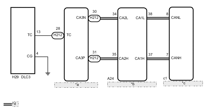
| *a | Hybrid Vehicle Control ECU Assembly |
| *b | Skid Control ECU (Brake Booster with Master Cylinder Assembly) |
| *c | Power Steering ECU Assembly |
| *d | CAN Communication Line |
CAUTION / NOTICE / HINT
Note
If the power steering ECU assembly has been replaced with a new one, perform assist map writing and torque sensor zero point calibration Click here.
Tech Tips
When the warning lights continue to blink, a ground short in the wiring of terminal TC of the DLC3 or an internal ground short in one or more ECUs is suspected.
PROCEDURE
-
CHECK CAN COMMUNICATION SYSTEM
-
Check for DTCs (See page for with Central Gateway ECU, Click here for without Central Gateway ECU).
Result Result Proceed to DTCs are not output. A DTCs are output (w/ Central Gateway ECU). B DTCs are output (w/o Central Gateway ECU). C
B 
GO TO CAN COMMUNICATION SYSTEM (w/ Central Gateway ECU) Click here
C
GO TO CAN COMMUNICATION SYSTEM (w/o Central Gateway ECU) Click here
A 
-
-
CHECK HARNESS AND CONNECTOR (TC of DLC3 - HYBRID VEHICLE CONTROL ECU ASSEMBLY)
-
Turn the power switch off.
-
Disconnect the H212 hybrid vehicle control ECU assembly connector.
-
Measure the resistance according to the value(s) in the table below.
Standard Resistance Tester Connection Condition Specified Condition H29-13 (TC) - H212-28 (TC) Always Below 1 Ω
NG
REPAIR OR REPLACE HARNESS OR CONNECTOR
OK
-
-
CHECK HARNESS AND CONNECTOR (CG of DLC3 - BODY GROUND)
-
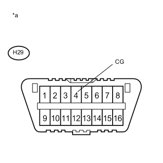
Text in Illustration *a Front view of DLC3 Measure the resistance according to the value(s) in the table below.
Standard Resistance Tester Connection Condition Specified Condition H29-4 (CG) - Body ground Always Below 1 Ω
NG
REPAIR OR REPLACE HARNESS OR CONNECTOR
OK
-
-
CHECK HARNESS AND CONNECTOR (TC of DLC3 - BODY GROUND)
-
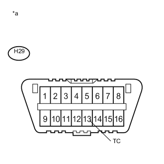
Text in Illustration *a Front view of DLC3 Measure the resistance according to the value(s) in the table below.
Standard Resistance Tester Connection Condition Specified Condition H29-13 (TC) - Body ground Always 10 kΩ or higher Tech Tips
If troubleshooting has been carried out according to Problem Symptoms Table, refer back to the table and proceed to the next step before replacing the part Click here.
Result Result Proceed to OK (for Manual tilt and manual telescopic steering column) A OK (for Power tilt and power telescopic steering column) B NG C
A
REPLACE POWER STEERING ECU ASSEMBLY Click here
B
REPLACE POWER STEERING ECU ASSEMBLY Click here
C
REPAIR OR REPLACE WIRE HARNESS OR EACH ECU
-