CAUTION / NOTICE / HINT
-
Because the left and right hoses are not interchangeable, verify the part number when installing the flexible hoses.
-
If the hoses are to be reused, connect them after checking the identification marks placed when each hose was disconnected.
-
Use the same procedure for the LH side and RH side.
-
The following procedure is for the LH side.
PROCEDURE
- Click here
INSTALL FRONT FLEXIBLE HOSE
-
Install a new clip to the front flexible hose.
Table 1. Text in Illustration *1 Clip *a Identification Mark Note:
-
Install the clip as far as it will go.
-
When installing the front flexible hose, face the identification mark to the outside of the vehicle and minimize twisting of the hose.
-
-
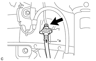
Using a union nut wrench, connect the brake line to the front flexible hose while holding the flexible hose with a wrench.
15 N*m 155 kgf*cm 11 ft.*lbf Note:
-
Do not bend or damage the brake line.
-
Do not allow any foreign matter such as dirt or dust to enter the brake line from the connecting points.
-
Use the formula to calculate special torque values for situations where the union nut wrench is combined with a torque wrench (Click here).
-
-
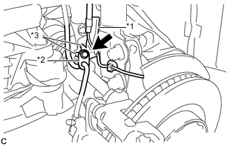
Install the front speed sensor clamp and front flexible hose to the shock absorber bracket with the bolt.
Table 2. Text in Illustration *1 Front Speed Sensor Clamp *2 Front Flexible Hose *3 Claw 19 N*m 192 kgf*cm 14 ft.*lbf Note:
-
Do not twist the wire harness for the front speed sensor when installing it.
-
Securely set the 2 claws of the front speed sensor clamp to the shock absorber bracket.
-
A bolt tightens the brake flexible hose and front speed sensor together. Make sure that the front flexible hose is positioned over the front speed sensor.
-
-
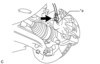
Connect the front flexible hose to the front disc brake cylinder assembly with a new union bolt and a new gasket.
Table 3. Text in Illustration *a Lock Hole 29 N*m 300 kgf*cm 22 ft.*lbf Note:Install the flexible hose lock securely into the lock hole in the front disc brake cylinder.
-
- Click here
CONNECT CABLE TO NEGATIVE AUXILIARY BATTERY TERMINAL
- Click here
BLEED BRAKE LINE
- Click here
INSTALL FRONT WHEEL
103 N*m 1049 kgf*cm 76 ft.*lbf