PROCEDURE
- Click here
INSTALL BRAKE ACTUATOR BRACKET ASSEMBLY
-
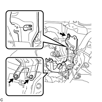
Engage the claw to set the brake actuator bracket assembly to the vehicle body.
Table 1. Text in Illustration *a Claw -
Install the 3 bolts to secure the brake actuator bracket assembly to the vehicle body.
19 N*m 194 kgf*cm 14 ft.*lbf Note:Tighten the 3 bolts in the order shown in the illustration.
-
Engage the clamp to install the front No. 5 brake tube to the brake actuator bracket assembly.
-
Engage the 2 clamps to install the 2 wire harnesses to the brake actuator bracket assembly.
-
- Click here
INSTALL FRONT WHEEL LH
103 N*m 1050 kgf*cm 76 ft.*lbf - Click here
INSTALL BRAKE BOOSTER PUMP ASSEMBLY
-
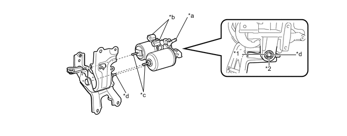
Insert the 2 studs of the brake booster pump assembly to the 2 holes of the brake actuator bracket assembly, and insert the pin of the brake actuator bracket assembly to the brake booster pump bushing.
Table 2. Text in Illustration *1 Brake Booster Pump Bushing *2 Brake Booster Pump Collar *a Union *b Connector *c Stud *d Pin Note:
-
Do not carry the brake booster pump assembly by the parts (*a), (*b) and (*c).
-
Do not drop the brake booster pump assembly when carrying it.
-
Do not kink or damage the brake lines.
-
Be careful not to allow any brake fluid to enter the connector.
-
When installing the brake booster pump assembly to the brake actuator bracket assembly, confirm that the brake booster pump collar and brake booster pump bushing are installed on the brake booster pump assembly.
-
If installing a new brake booster pump assembly, do not remove the hole plug before connecting the brake lines because the brake booster pump assembly is filled with brake fluid.
-
-
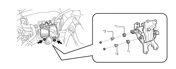
Install the 2 brake actuator case collars, 2 brake booster pump bushings and 2 nuts to the brake actuator bracket assembly.
Table 3. Text in Illustration *1 Brake Booster Pump Bushing *2 Brake Actuator Case Collar 5.4 N*m 55 kgf*cm 48 in.*lbf -
Using a union nut wrench, connect the front No. 1 brake tube to the brake booster pump assembly.
15 N*m 155 kgf*cm 11 ft.*lbf Note:Use the formula to calculate special torque values for situations where the union nut wrench is combined with a torque wrench (Click here).
-
Connect the 2 connectors to the brake booster pump assembly.
-
- Click here
INSTALL RESERVOIR BRACKET
-
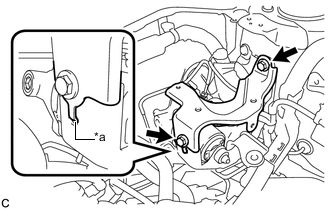
Engage the claw to set the reservoir bracket to the brake actuator bracket assembly.
Table 4. Text in Illustration *a Claw -
Install the 2 bolts to secure the reservoir bracket to the brake actuator bracket assembly.
19 N*m 194 kgf*cm 14 ft.*lbf
-
- Click here
CONNECT BRAKE ACTUATOR HOSE
-
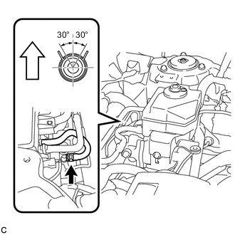
Connect the brake actuator hose to the brake booster pump assembly with the clip.
Table 5. Text in Illustration 
Up Note:
-
When connecting the brake actuator hose, face the identification mark up.
-
Match the identification mark of the brake actuator hose and the rib of the brake booster pump assembly.
-
Make sure to install the hose to the proper location.
-
Install the clip within the range shown in the illustration.
-
-
- Click here
BLEED RESERVOIR TUBE
- Click here
INSTALL RESERVOIR TUBE
- Click here
INSTALL BRAKE MASTER CYLINDER RESERVOIR ASSEMBLY
- Click here
FILL RESERVOIR WITH BRAKE FLUID
- Click here
CONNECT CABLE TO NEGATIVE AUXILIARY BATTERY TERMINAL
- Click here
BLEED BRAKE SYSTEM
- Click here
INSTALL AIR CLEANER CASE SUB-ASSEMBLY
- Click here
INSTALL AIR CLEANER FILTER ELEMENT SUB-ASSEMBLY
- Click here
INSTALL AIR CLEANER CAP SUB-ASSEMBLY
- Click here
INSTALL INLET AIR CLEANER ASSEMBLY
- Click here
INSTALL COOL AIR INTAKE DUCT SEAL
- Click here
INSTALL FRONT OUTER COWL TOP PANEL SUB-ASSEMBLY
- Click here
INSTALL WINDSHIELD WIPER MOTOR AND LINK ASSEMBLY
Tip:Use the same procedure as for LHD (Click here).