BRAKE BOOSTER PUMP(for LHD) INSTALLATION
PROCEDURE
-
INSTALL BRAKE BOOSTER PUMP ASSEMBLY
-
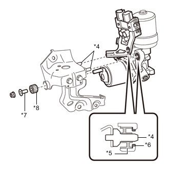
Insert the stud of the brake booster pump assembly to the hole of the brake actuator bracket assembly, and insert the 2 pins of the brake actuator bracket assembly to the 2 brake booster pump bushings (*5).
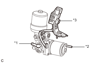
Text in Illustration *1 Union *2 Stud *3 Connector Box and Wire Harness *4 Pin *5 Brake Booster Pump Bushing *6 Brake Booster Pump Collar *7 Brake Actuator Case Collar *8 Brake Booster Pump Bushing Note
-
Do not carry the brake booster pump assembly by the parts shown in bold (*1, *2 and *3) in the illustration.
-
Do not drop the brake booster pump assembly when carrying it.
-
Be careful not to allow any brake fluid to enter the connector.
-
When installing the brake booster pump assembly to the brake actuator bracket assembly, confirm that the 2 brake booster pump collars (*6) and 2 brake booster pump bushings (*5) are installed on the brake booster pump assembly.
-
Do not remove the hole plugs before installing a new brake booster pump assembly because the brake booster pump assembly is filled with brake fluid.
-
-
Install the brake actuator case collar (*7), brake booster pump bushing (*8) and brake booster pump assembly to the brake actuator bracket assembly with the nut.
- Torque:
- 5.4 N*m { 55 kgf*cm, 48 in.*lbf }
-
Engage the wire harness clamp to the brake actuator bracket assembly.
-
-
INSTALL NO. 2 BRAKE ACTUATOR HOSE
-
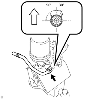
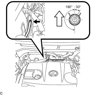
Install the No. 2 brake actuator hose to the brake booster pump assembly with the clip.
Text in Illustration 
Up Note
-
Match the identification mark of the No. 2 brake actuator hose and the rib of the brake booster pump assembly.
-
Install the clip within the range shown in the illustration.
-
-
-
INSTALL BRAKE BOOSTER PUMP ASSEMBLY WITH BRACKET
-
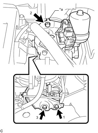
Text in Illustration *a Claw Engage the claw to set the brake booster pump assembly with bracket to the vehicle body.
Note
Do not kink or damage the brake line, suction pipe sub-assembly or air conditioning tube and accessory assembly.
-
Install the 3 bolts to secure the brake booster pump assembly with bracket to the vehicle body.
- Torque:
- 19 N*m { 194 kgf*cm, 14 ft.*lbf }
Note
Tighten the 3 bolts in the order shown in the illustration.
-
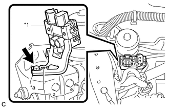
Text in Illustration *1 Connector Box *a Claw Engage the claw to set the connector box to the brake actuator bracket assembly.
-
Install the bolt to secure the connector box to the brake actuator bracket assembly.
- Torque:
- 8.0 N*m { 82 kgf*cm, 71 in.*lbf }
-
Connect the 2 connectors to the brake booster pump assembly.
-
-
CONNECT FRONT NO. 1 BRAKE TUBE
-
Using a union nut wrench, connect the front No. 1 brake tube to the brake booster pump assembly.
- Torque:
- 15 N*m { 155 kgf*cm, 11 ft.*lbf }
Note
Use the formula to calculate special torque values for situations where the union nut wrench is combined with a torque wrench Click here.
-
-
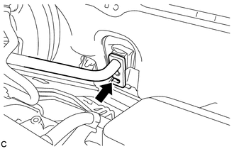
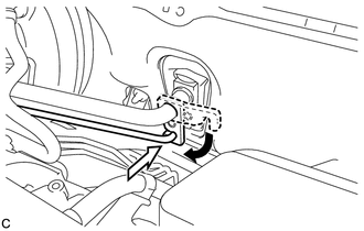
CONNECT NO. 2 BRAKE ACTUATOR HOSE
-
Connect the No. 2 brake actuator hose to the No. 1 brake actuator tube with the clip.
Text in Illustration Up Note
-
Match the identification mark of the No. 2 brake actuator hose and No. 1 brake actuator tube.
-
Install the clip within the range shown in the illustration.
-
-
-
BLEED NO. 1 BRAKE ACTUATOR TUBE
-
INSTALL NO. 1 BRAKE ACTUATOR TUBE
-
INSTALL BRAKE MASTER CYLINDER RESERVOIR ASSEMBLY
-
INSTALL SUCTION PIPE SUB-ASSEMBLY
-
Remove the vinyl tape from the openings of the disconnected parts.
-
Sufficiently apply compressor oil to a new O-ring, the fitting surface of the suction pipe sub-assembly and air conditioning unit.
Compressor oil ND-OIL 11 or equivalent Note
Do not use any compressor oil other than ND-OIL 11 or equivalent. If any compressor oil other than ND-OIL 11 or equivalent is used, compressor motor insulation performance may decrease, resulting in a leakage of electric power.
-
Install the O-ring to the suction pipe sub-assembly.
Note
Keep the O-ring and O-ring fitting surfaces free from dirt or any foreign matter.
-
Insert the suction pipe sub-assembly to the air conditioning unit.
Note
-
Insert the pipe joint into the fitting hole securely.
-
Do not deform the piping.
-
Do not damage the plastic clamp.
-
-
-
INSTALL AIR CONDITIONER TUBE AND ACCESSORY ASSEMBLY
-
Remove the vinyl tape from the openings of the disconnected parts.
-
Sufficiently apply compressor oil to a new O-ring, the fitting surface of the air conditioning tube and accessory assembly and air conditioning unit.
Compressor oil ND-OIL 11 or equivalent Note
Do not use any compressor oil other than ND-OIL 11 or equivalent. If any compressor oil other than ND-OIL 11 or equivalent is used, compressor motor insulation performance may decrease, resulting in a leakage of electric power.
-
Install the O-ring to the air conditioning tube and accessory assembly.
Note
Keep the O-ring and O-ring fitting surface free from dirt or any foreign matter.
-
Insert the air conditioning tube and accessory assembly to the air conditioning unit.
Note
Insert the pipe joint into the fitting hole securely.
-
Turn the hook connector and install the bolt.
- Torque:
- 9.8 N*m { 100 kgf*cm, 87 in.*lbf }
-
-
FILL RESERVOIR WITH BRAKE FLUID
-
CONNECT CABLE TO NEGATIVE AUXILIARY BATTERY TERMINAL
-
BLEED BRAKE SYSTEM
-
INSTALL AIR CLEANER CASE SUB-ASSEMBLY
-
INSTALL AIR CLEANER FILTER ELEMENT SUB-ASSEMBLY
-
INSTALL AIR CLEANER CAP SUB-ASSEMBLY
-
INSTALL INLET AIR CLEANER ASSEMBLY
-
INSTALL COOL AIR INTAKE DUCT SEAL
-
CHARGE AIR CONDITIONING SYSTEM WITH REFRIGERANT
-
WARM UP COMPRESSOR
-
INSPECT FOR REFRIGERANT LEAK
-
INSTALL FRONT OUTER COWL TOP PANEL SUB-ASSEMBLY
-
INSTALL WINDSHIELD WIPER MOTOR AND LINK ASSEMBLY