Info Added 2017-08-02
PROCEDURE
- Click here
INSTALL BRAKE BOOSTER GASKET
-
Install a new brake booster gasket to the brake booster with master cylinder assembly.
-
- Click here
INSTALL BRAKE BOOSTER WITH MASTER CYLINDER ASSEMBLY
-
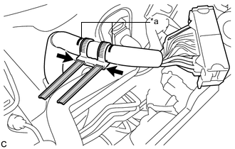
Align the matchmarks on the wire harness and a new wire harness clamp, and install it to the wire harness.
Table 1. Text in Illustration *a Matchmark 
Cut 
Excess Note:Make sure to install the wire harness clamp in the correct direction.
-
Tighten the bands of the clamp and cut off the excess.
-
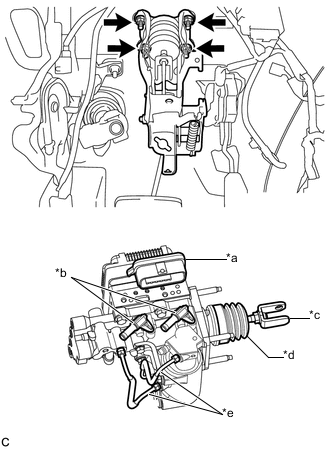
Install the brake booster with master cylinder assembly with the 4 nuts.
Table 2. Text in Illustration *a Connector Portion *b Union *c Brake Master Cylinder Push Rod Clevis *d Boot *e Front No. 2 Brake Tube 13 N*m 131 kgf*cm 9 ft.*lbf Note:
-
Do not kink or damage the brake lines.
-
Do not carry the brake booster with master cylinder assembly by the parts shown in bold in the illustration.
-
Be careful not to allow any brake fluid to enter the connector.
-
If installing a new brake booster with master cylinder assembly, do not remove the hole plugs before connecting the brake lines because the brake booster with master cylinder is filled with brake fluid.
-
-
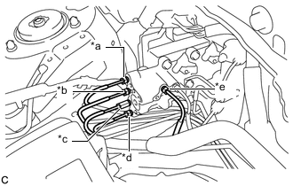
Temporarily tighten each brake line to the correct position on the brake booster with master cylinder assembly as shown in the illustration.
Table 3. Text in Illustration *a to Front Wheel Cylinder LH (Way) *b to Rear Wheel Cylinder RH *c to Brake Booster Pump Assembly *d to Rear Wheel Cylinder LH *e to Front Wheel Cylinder RH -
Using a union nut wrench, fully tighten each brake line.
15 N*m 155 kgf*cm 11 ft.*lbf Note:
-
Do not kink or damage the brake lines.
-
Use the formula to calculate special torque values for situations where the union nut wrench is combined with a torque wrench (Click here).
-
-
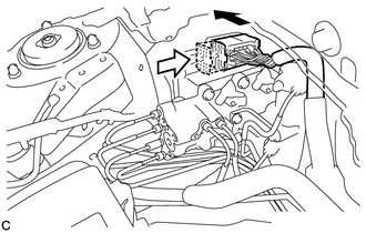
Connect the connector to the brake booster with master cylinder assembly.
Table 4. Text in Illustration Connect the connector 
Lock the lock lever Note:
-
Make sure that the connector can be connected smoothly. Do not allow water, oil or dirt to enter.
-
Make sure that the connector lock is locked securely.
-
-
Push in the wire harness clamp to install it to the brake booster with master cylinder assembly.
-
- Click here
INSTALL PUSH ROD PIN
- Click here
CONNECT NO. 1 RESERVOIR HOSE
-
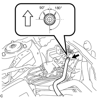
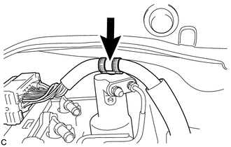
Connect the No. 1 reservoir hose to the brake booster with master cylinder assembly with the clip.
Table 5. Text in Illustration Up Note:
-
When connecting the No. 1 reservoir hose, face the identification mark up.
-
Match the identification mark of the No. 1 reservoir hose and the rib of the brake booster with master cylinder assembly.
-
Make sure to install the hose to the proper location.
-
Install the clip within the range shown in the illustration.
-
-
- Click here
CONNECT NO. 2 RESERVOIR HOSE
-
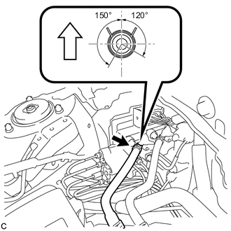
Connect the No. 2 reservoir hose to the brake booster with master cylinder assembly with the clip.
Table 6. Text in Illustration Up Note:
-
When connecting the No. 2 reservoir hose, face the identification mark up.
-
Match the identification mark of the No. 2 reservoir hose and the identification mark of the brake booster with master cylinder assembly.
-
Make sure to install the hose to the proper location.
-
Install the clip within the range shown in the illustration.
-
-
- Click here
BLEED RESERVOIR TUBE
-
Add brake fluid into the brake master cylinder reservoir assembly.
-

Lift up the brake master cylinder reservoir assembly as far as possible and rock it back and forth to bleed air from the reservoir tube.
Table 7. Text in Illustration *1 Reservoir Tube Note:
-
Do not damage the hoses or tubes.
-
Do not spill the brake fluid.
-
Continue this procedure until only a minor amount of air remains in the brake actuator tube.
-
-
- Click here
INSTALL RESERVOIR TUBE
-
Install the reservoir tube to the vehicle body with the 2 bolts and nut.
8.5 N*m 87 kgf*cm 75 in.*lbf
-
- Click here
INSTALL BRAKE MASTER CYLINDER RESERVOIR ASSEMBLY
-
Install the brake master cylinder reservoir assembly to the reservoir bracket with the 2 bolts.
8.5 N*m 87 kgf*cm 75 in.*lbf
-
- Click here
FILL RESERVOIR WITH BRAKE FLUID
- Click here
CONNECT CABLE TO NEGATIVE AUXILIARY BATTERY TERMINAL
- Click here
BLEED BRAKE SYSTEM
- Click here
INSTALL AIR CLEANER CASE SUB-ASSEMBLY
- Click here
INSTALL AIR CLEANER FILTER ELEMENT SUB-ASSEMBLY
- Click here
INSTALL AIR CLEANER CAP SUB-ASSEMBLY
- Click here
INSTALL INLET AIR CLEANER ASSEMBLY
- Click here
INSTALL COOL AIR INTAKE DUCT SEAL
- Click here
INSTALL FRONT OUTER COWL TOP PANEL SUB-ASSEMBLY
-
Install the front outer cowl top panel sub-assembly with the 10 bolts.
10 N*m 102 kgf*cm 7 ft.*lbf -
Engage the 2 clamps to install the wire harness to the front outer cowl top panel sub-assembly.
-
- Click here
INSTALL WINDSHIELD WIPER MOTOR AND LINK ASSEMBLY
Tip:Use the same procedure as for LHD (Click here).
- Click here
INSPECT AND ADJUST BRAKE PEDAL
- Click here
OBTAIN ZERO POINT OF YAW RATE AND ACCELERATION SENSOR
Tip:After the brake booster with master cylinder assembly is replaced, obtain the zero point of the yaw rate and acceleration sensor (Click here).