BRAKE BOOSTER(for LHD) INSTALLATION
Info Added 2017-08-02 ![]()
PROCEDURE
-
INSTALL BRAKE BOOSTER GASKET
-
Install a new brake booster gasket to the brake booster with master cylinder assembly.
-
-
INSTALL BRAKE BOOSTER WITH MASTER CYLINDER ASSEMBLY
-
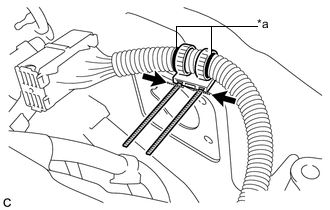
Text in Illustration *a Matchmark 
Cut 
Disposal Portion Align the matchmarks on the wire harness and a new wire harness clamp, and install it to the wire harness.
Note
Make sure to install the wire harness clamp in the correct direction.
-
Tighten the bands of the clamp and cut off the excess.
-
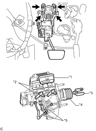
Text in Illustration *1 Connector Portion *2 Union *3 Push Rod Clevis *4 Boot *5 Front No. 2 Brake Tube Install the brake booster with master cylinder assembly with the 4 nuts.
- Torque:
- 13 N*m { 131 kgf*cm, 9 ft.*lbf }
Note
-
Do not kink or damage the brake lines.
-
Do not carry the brake booster with master cylinder assembly by the parts shown in bold in the illustration.
-
Be careful not to allow any brake fluid to enter the connector.
-
If installing a new brake booster with master cylinder assembly, do not remove the hole plugs before connecting the brake lines because the brake booster with master cylinder is filled with brake fluid.
-
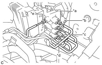
Text in Illustration *a to Front Wheel Cylinder LH *b to Rear Wheel Cylinder RH *c to Brake Booster Pump Assembly *d to Rear Wheel Cylinder LH *e to Front Wheel Cylinder RH Temporarily tighten each brake line to the correct position on the brake booster with master cylinder assembly as shown in the illustration.
-
Using a union nut wrench, fully tighten each brake line.
- Torque:
- 15 N*m { 155 kgf*cm, 11 ft.*lbf }
Note
-
Do not kink or damage the brake lines.
-
Use the formula to calculate special torque values for situations where the union nut wrench is combined with a torque wrench Click here.
-
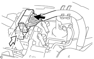
Connect the connector to the brake booster with master cylinder assembly.
Text in Illustration Connect the connector 
Lock the lock lever Note
-
Make sure that the connector can be connected smoothly. Do not allow water, oil or dirt to enter.
-
Make sure that the connector lock is locked securely.
-
-
Push in the wire harness clamp to install it to the brake booster with master cylinder assembly.
-
-
INSTALL RESERVOIR BRACKET
-
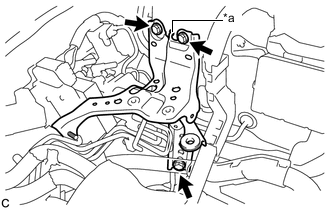
Text in Illustration *a Claw Engage the claw to set the reservoir bracket to the vehicle body.
-
Install the 3 bolts to secure the reservoir bracket to the vehicle body.
- Torque:
- 19 N*m { 194 kgf*cm, 14 ft.*lbf }
-
Engage the 2 clamps to install the wire harness to the reservoir bracket.
-
-
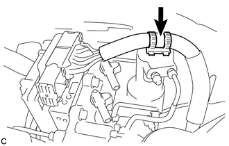
CONNECT NO. 1 RESERVOIR HOSE
-
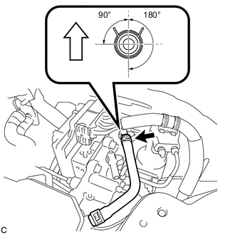
Connect the No. 1 reservoir hose to the brake booster with master cylinder assembly with the clip.
Text in Illustration Up Note
-
When connecting the No. 1 reservoir hose, face the identification mark up.
-
Match the identification mark of the No. 1 reservoir hose and the rib of the brake booster with master cylinder assembly.
-
Make sure to install the hose to the proper location.
-
Install the clip within the range shown in the illustration.
-
-
-
CONNECT NO. 2 RESERVOIR HOSE
-
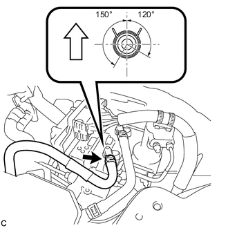
Connect the No. 2 reservoir hose to the brake booster with master cylinder assembly with the clip.
Text in Illustration Up Note
-
When connecting the No. 2 reservoir hose, face the identification mark up.
-
Match the identification mark of the No. 2 reservoir hose and the identification mark of the brake booster with master cylinder assembly.
-
Make sure to install the hose to the proper location.
-
Install the clip within the range shown in the illustration.
-
-
-
BLEED NO. 1 BRAKE ACTUATOR TUBE
-
Add brake fluid into the brake master cylinder reservoir assembly.
-
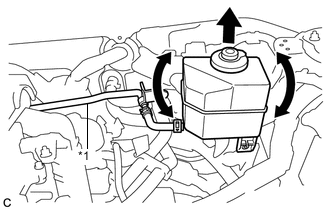
Text in Illustration *1 No. 1 Brake Actuator Tube Lift up the brake master cylinder reservoir assembly as far as possible and rock it back and forth to bleed air from the No. 1 brake actuator tube.
Note
-
Do not damage the hoses or tubes.
-
Do not spill the brake fluid.
-
Continue this procedure until only a minor amount of air remains in the No. 1 brake actuator tube.
-
-
-
INSTALL NO. 1 BRAKE ACTUATOR TUBE
-
Install the No. 1 brake actuator tube to the vehicle body with the nut.
- Torque:
- 8.5 N*m { 87 kgf*cm, 75 in.*lbf }
-
Install the nut and engage the clamp.
- Torque:
- 8.5 N*m { 87 kgf*cm, 75 in.*lbf }
-
-
INSTALL BRAKE MASTER CYLINDER RESERVOIR ASSEMBLY
-
Install the brake master cylinder reservoir assembly to the reservoir bracket with the 2 bolts.
- Torque:
- 8.5 N*m { 87 kgf*cm, 75 in.*lbf }
-
-
INSTALL PUSH ROD PIN
-
FILL RESERVOIR WITH BRAKE FLUID
-
CONNECT CABLE TO NEGATIVE AUXILIARY BATTERY TERMINAL
-
BLEED BRAKE SYSTEM
-
INSTALL AIR CLEANER CASE SUB-ASSEMBLY
-
INSTALL AIR CLEANER FILTER ELEMENT SUB-ASSEMBLY
-
INSTALL AIR CLEANER CAP SUB-ASSEMBLY
-
INSTALL INLET AIR CLEANER ASSEMBLY
-
INSTALL COOL AIR INTAKE DUCT SEAL
-
INSTALL FRONT OUTER COWL TOP PANEL SUB-ASSEMBLY
-
Install the front outer cowl top panel sub-assembly with the 10 bolts.
- Torque:
- 10 N*m { 102 kgf*cm, 7 ft.*lbf }
-
Engage the 2 clamps to install the wire harness to the front outer cowl top panel sub-assembly.
-
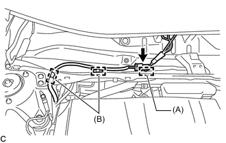
Connect the connector to install the wire harness to the front outer cowl top panel sub-assembly.
-
Engage the 2 clamps (B).
-
w/ Wiper Deicer System:
Engage the clamp (A).
-
-
INSTALL WINDSHIELD WIPER MOTOR AND LINK ASSEMBLY
-
INSPECT AND ADJUST BRAKE PEDAL
-
OBTAIN ZERO POINT OF YAW RATE AND ACCELERATION SENSOR
Tech Tips
After the brake booster with master cylinder assembly is replaced, obtain the zero point of the yaw rate and acceleration sensor Click here.