DESCRIPTION
Connecting terminals TC and CG of the DLC3 causes the ECU to display the DTC by blinking the ABS warning, brake warning / yellow (minor malfunction) and slip indicator lights.
WIRING DIAGRAM
When the warning lights blink without terminals TC and CG connected, a ground short in the wiring of terminal TC of the DLC3 or an internal ground short in one or more ECUs is suspected.
CAUTION / NOTICE / HINT
When replacing the skid control ECU (brake booster with master cylinder assembly), perform initialization and calibration of the linear solenoid valve (Click here).
PROCEDURE
- Click here
CHECK CAN COMMUNICATION SYSTEM
-
Check if CAN communication system DTCs are output (Click here).
Result Result Proceed to DTCs are not output. A DTCs are output. B
- AClick here
- B
INSPECT CAN COMMUNICATION SYSTEM (Click here)
-
- Click here
CHECK HARNESS AND CONNECTOR (TC of DLC3 - POWER MANAGEMENT CONTROL ECU)
-
Disconnect the H1 power management control ECU connector.
-
Measure the resistance according to the value(s) in the table below.
Standard Resistance Tester Connection Condition Specified Condition H29-13 (TC) - H1-11 (TC) Always Below 1 Ω
- OKClick here
- NG
REPAIR OR REPLACE HARNESS OR CONNECTOR
-
- Click here
CHECK HARNESS AND CONNECTOR (CG of DLC3 - BODY GROUND)
-
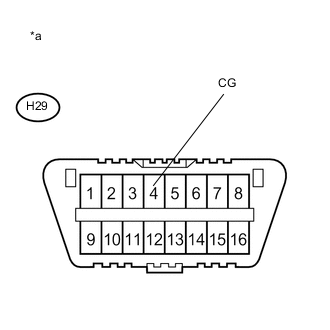
Measure the resistance according to the value(s) in the table below.
Standard Resistance Tester Connection Condition Specified Condition H29-4 (CG) - Body ground Always Below 1 Ω Table 2. Text in Illustration *a Front view of DLC3
- OKClick here
- NG
REPAIR OR REPLACE HARNESS OR CONNECTOR
-
- Click here
CHECK HARNESS AND CONNECTOR (TC of DLC3 - BODY GROUND)
-
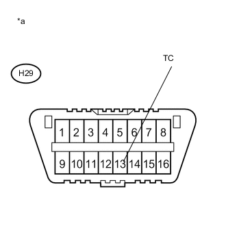
Measure the resistance according to the value(s) in the table below.
Standard Resistance Tester Connection Condition Specified Condition H29-13 (TC) - Body ground Always 10 kΩ or higher Table 3. Text in Illustration *a Front view of DLC3 Tip:If troubleshooting has been carried out according to Problem Symptoms Table, refer back to the table and proceed to the next step before replacing the part (Click here).
- OK
REPLACE BRAKE BOOSTER WITH MASTER CYLINDER ASSEMBLY (Click here)
- NG
REPAIR OR REPLACE WIRE HARNESS OR EACH ECU
-