DESCRIPTION
A buzzer sounds to alert the driver when the vehicle-to-vehicle distance becomes less than the set value (for vehicles with a dynamic radar cruise control, pre-crash safety control or lane departure alert control).
WIRING DIAGRAM
CAUTION / NOTICE / HINT
-
When replacing the skid control ECU (brake booster with master cylinder assembly), perform initialization and calibration of the linear solenoid valve (Click here).
-
Inspect the fuses for circuits related to this system before performing the following inspection procedure.
PROCEDURE
- Click here
CHECK BUZZER OPERATION
-
Confirm problem symptoms of the skid control buzzer assembly according to the customer problem analysis.
Result Result Proceed to Buzzer does not sound. A Buzzer sounds constantly. B
-
- Click here
PERFORM ACTIVE TEST USING GTS (SKID CONTROL BUZZER ASSEMBLY)
-
Connect the GTS to the DLC3.
-
Turn the power switch on (IG).
-
Select the Active Test on the GTS (Click here).
Table 2. ABS/VSC/TRC Tester Display Test Part Control Range Diagnostic Note DSS Signal Buzzer Skid control buzzer assembly Buzzer ON/OFF Buzzer can be heard -
Check that the buzzer sounds/stops when turning the skid control buzzer assembly on/off using the GTS.
Result Result Proceed to Buzzer does not sound. A Buzzer sounds/stops. B Tip:If troubleshooting has been carried out according to Problem Symptoms Table, refer back to the table and proceed to the next step (Click here).
- AClick here
- B
USE SIMULATION METHOD TO CHECK (Click here)
-
- Click here
CHECK HARNESS AND CONNECTOR (POWER SOURCE TERMINAL)
-
Turn the power switch off.
-
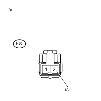
Disconnect the H65 skid control buzzer assembly connector.
-
Turn the power switch on (IG).
-
Measure the voltage according to the value(s) in the table below.
Standard Voltage Tester Connection Condition Specified Condition H65-2 (IG1) - Body ground Power switch on (IG) 11 to 14 V Table 3. Text in Illustration *a Front view of wire harness connector
(to Skid Control Buzzer Assembly)
- OKClick here
- NG
REPAIR OR REPLACE HARNESS OR CONNECTOR (POWER SOURCE CIRCUIT)
-
- Click here
INSPECT SKID CONTROL BUZZER ASSEMBLY
-
Turn the power switch off.
-
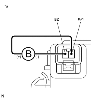
Connect a negative (-) lead from the auxiliary battery to terminal 1 (BZ), and a positive (+) lead to terminal 2 (IG1) of the skid control buzzer assembly, and then check that the buzzer sounds.
OK The skid control buzzer assembly sounds. Table 4. Text in Illustration *a Component without harness connected
(Skid Control Buzzer Assembly)
- OKClick here
- NG
REPLACE SKID CONTROL BUZZER ASSEMBLY (Click here)
-
- Click here
CHECK HARNESS AND CONNECTOR (BRAKE BOOSTER WITH MASTER CYLINDER ASSEMBLY - SKID CONTROL BUZZER ASSEMBLY)
-
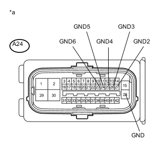
Disconnect the A24 skid control ECU (brake booster with master cylinder assembly) connector 2 minutes after the power switch is turned off.
Tip:Do not open/close the driver door within 2 minutes after the power switch is turned off.
-
Measure the resistance according to the value(s) in the table below.
Standard Resistance Tester Connection Condition Specified Condition A24-13 (BZ) - H65-1 (BZ) Always Below 1 Ω A24-13 (BZ) - Body ground Always 10 kΩ or higher
- OKClick here
- NG
REPAIR OR REPLACE HARNESS OR CONNECTOR
-
- Click here
CHECK HARNESS AND CONNECTOR (GND TERMINAL)
-
Measure the resistance according to the value(s) in the table below.
Standard Resistance Tester Connection Condition Specified Condition A24-28 (GND) - Body ground Always Below 1 Ω A24-27 (GND2) - Body ground Always Below 1 Ω A24-26 (GND3) - Body ground Always Below 1 Ω A24-25 (GND4) - Body ground Always Below 1 Ω A24-24 (GND5) - Body ground Always Below 1 Ω A24-23 (GND6) - Body ground Always Below 1 Ω Table 5. Text in Illustration *a Front view of wire harness connector
(to Skid Control ECU (Brake Booster with Master Cylinder Assembly))
Tip:If troubleshooting has been carried out according to Problem Symptoms Table, refer back to the table and proceed to the next step before replacing the part (Click here).
- OK
REPLACE BRAKE BOOSTER WITH MASTER CYLINDER ASSEMBLY (Click here)
- NG
REPAIR OR REPLACE HARNESS OR CONNECTOR (GND CIRCUIT)
-
- Click here
INSPECT BRAKE BOOSTER WITH MASTER CYLINDER ASSEMBLY
-
Disconnect the A24 skid control ECU (brake booster with master cylinder assembly) connector.
-
Check the skid control buzzer assembly operation.
Result Result Proceed to Buzzer stops. A Buzzer sounds constantly. B Tip:If troubleshooting has been carried out according to Problem Symptoms Table, refer back to the table and proceed to the next step before replacing the part (Click here).
- A
REPLACE BRAKE BOOSTER WITH MASTER CYLINDER ASSEMBLY (Click here)
- BClick here
-
- Click here
REPLACE SKID CONTROL BUZZER ASSEMBLY
-
Reconnect the A24 skid control ECU (brake booster with master cylinder assembly) connector.
-
Replace the skid control buzzer assembly (Click here).
-
Check the skid control buzzer assembly operation.
Result Result Proceed to Buzzer stops. A Buzzer sounds constantly. B
- A
END
- BClick here
-
- Click here
CHECK IF CONNECTOR IS SECURELY CONNECTED
-
Gently jiggle the connectors and wire harnesses and check the skid control buzzer assembly operation.
Result Result Proceed to Buzzer stops. A Buzzer sounds constantly. B
- A
END
- B
REPAIR OR REPLACE HARNESS OR CONNECTOR
-