CAUTION / NOTICE / HINT
-
Use the same procedure for the LH side and RH side.
-
The following procedure is for the LH side.
-
If the sensor rotor needs to be replaced, replace the front drive outboard joint shaft assembly.
PROCEDURE
- Click here
PRECAUTION
Note:After turning the power switch off, waiting time may be required before disconnecting the cable from the negative (-) auxiliary battery terminal. Therefore, make sure to read the disconnecting the cable from the negative (-) auxiliary battery terminal notice before proceeding with work (Click here).
- Click here
DISCONNECT CABLE FROM NEGATIVE AUXILIARY BATTERY TERMINAL
- Click here
REMOVE FRONT FENDER LINER
Tip:Use the same procedure for the LH side and RH side (Click here).
- Click here
REMOVE FRONT SPEED SENSOR
-
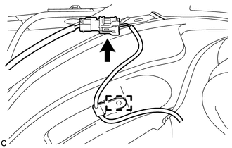
Disconnect the connector and disengage the clamp.
-
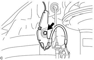
Remove the bolt and front speed sensor clamp from the body.
-
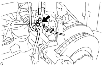
Remove the bolt, front flexible hose and front speed sensor clamp together from the front shock absorber assembly.
Table 1. Text in Illustration *1 Front Speed Sensor Clamp *2 Front Flexible Hose -
Disengage the clamp from the front shock absorber assembly.
-
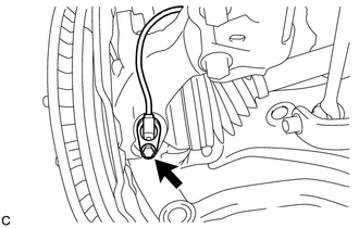
Remove the bolt and front speed sensor from the steering knuckle.
Note:
-
Prevent foreign matter from attaching to the front speed sensor tip.
-
Clean the speed sensor installation hole and the contact surfaces every time the front speed sensor is removed.
-
-