ELECTRONICALLY CONTROLLED BRAKE SYSTEM, Diagnostic DTC:C1252/52, C1253/53

| DTC Code | DTC Name |
|---|---|
| C1252/52 | Brake Booster Pump Motor on Time Abnormally Long |
| C1253/53 | Pump Motor Relay Malfunction |
DESCRIPTION
The skid control ECU (brake booster with master cylinder assembly) detects decreases in the accumulator pressure according to the data from the accumulator pressure sensor, and then starts and stops the pump motor by operating the motor relay.
| DTC No. | INF Code | DTC Detection Condition | Trouble Area |
|---|---|---|---|
| C1252/52 | 311 | The pump motor is operating continuously for 178 seconds or more. (When relay is malfunctioning for 98 seconds or more.) |
|
| C1253/53 | 321 | With the IG1 terminal voltage 9.5 V or more, the motor drive monitor remains off for 0.2 seconds or more after a motor drive on request. |
|
| ↑ | 322 | The motor drive monitor remains on for 2 seconds or more after a motor drive off request. |
|
| ↑ | 323 | The skid control ECU (brake booster with master cylinder assembly) internal motor drive logical inconsistency continues for 2 seconds or more. | Skid control ECU (Brake booster with master cylinder assembly) |
| ↑ | 324 | An open circuit is detected in both skid control ECU (brake booster with master cylinder assembly) internal motor relays 1 and 2. |
|
| ↑ | 325 | An open circuit is detected in both skid control ECU (brake booster with master cylinder assembly) internal motor relays 1 and 3. | ↑ |
| ↑ | 326 | An open circuit is detected in both skid control ECU (brake booster with master cylinder assembly) internal motor relays 2 and 3. | ↑ |
| ↑ | 327 | An open circuit is detected in skid control ECU (brake booster with master cylinder assembly) internal motor relay 1. | ↑ |
| ↑ | 328 | An open circuit is detected in skid control ECU (brake booster with master cylinder assembly) internal motor relay 2. | ↑ |
| ↑ | 329 | An open circuit is detected in skid control ECU (brake booster with master cylinder assembly) internal motor relay 3. | ↑ |
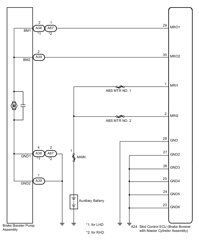
WIRING DIAGRAM
CAUTION / NOTICE / HINT
Note
-
When replacing the skid control ECU (brake booster with master cylinder assembly) or brake actuator (brake booster with master cylinder assembly), perform initialization and calibration of the linear solenoid valve Click here.
-
Inspect the fuses for circuits related to this system before performing the following inspection procedure.
PROCEDURE
-
PERFORM ACTIVE TEST USING GTS (ABS MOTOR RELAY)
-
Connect the GTS to the DLC3.
-
Turn the power switch on (IG).
-
Select the Active Test on the GTS Click here.
ABS/VSC/TRC Tester Display Test Part Control Range Diagnostic Note ECB* Motor Relay ABS motor relay Relay ON/OFF - *: Electronically Controlled Brake System
-
Select the Data List on the GTS Click here.
ABS/VSC/TRC Tester Display Measurement Item/Range Normal Condition Diagnostic Note ECB* Motor Relay ABS motor relay / ON or OFF ON: Relay on
OFF: Relay off
- *: Electronically Controlled Brake System
-
Check the operating condition of the ABS motor relay when operating it using the GTS.
Result Result Proceed to ABS motor relay in the Data List turns ON/OFF using the Active Test. A ABS motor relay in the Data List does not change using the Active Test. B
B 
CHECK HARNESS AND CONNECTOR (MRI TERMINAL) Click here
A 
-
-
INSPECT BRAKE BOOSTER PUMP ASSEMBLY
-
Turn the power switch off.
-
Make sure that there is no looseness at the locking part and the connecting part of the connectors.
-
Disconnect the A38, A39 and/or A67 brake booster pump assembly connectors.
-
Measure the resistance according to the value(s) in the table below.
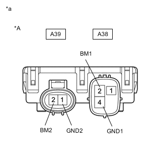
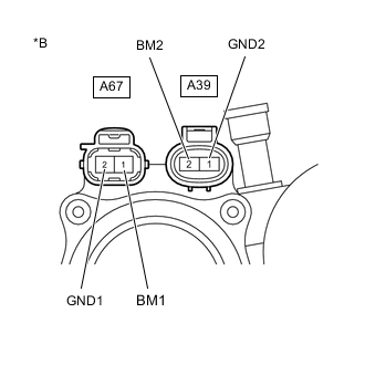
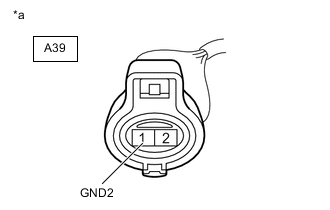
Standard Resistance for LHD Tester Connection Condition Specified Condition A38-2 (BM1) - A38-4 (GND1) Always Below 10 Ω A39-2 (BM2) - A39-1 (GND2) Always Below 10 Ω A38-2 (BM1) - A39-2 (BM2) Always Below 1 Ω A38-4 (GND1) - A39-1 (GND2) Always Below 1 Ω for RHD Tester Connection Condition Specified Condition A67-1 (BM1) - A67-2 (GND1) Always Below 10 Ω A39-2 (BM2) - A39-1 (GND2) Always Below 10 Ω A67-1 (BM1) - A39-2 (BM2) Always Below 1 Ω A67-2 (GND1) - A39-1 (GND2) Always Below 1 Ω Text in Illustration *A for LHD *B for RHD *a Component without harness connected
(Brake Booster Pump Assembly)
Result Result Proceed to OK A NG (for LHD) B NG (for RHD) C
B 
REPLACE BRAKE BOOSTER PUMP ASSEMBLY Click here
C
REPLACE BRAKE BOOSTER PUMP ASSEMBLY Click here
A
-
-
CHECK HARNESS AND CONNECTOR (GND TERMINAL)
-
Measure the resistance according to the value(s) in the table below.
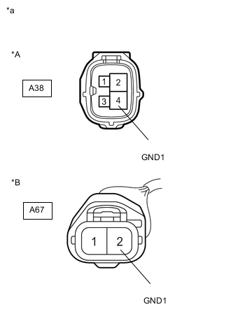
Standard Resistance for LHD Tester Connection Condition Specified Condition A38-4 (GND1) - Body ground Always Below 1 Ω A39-1 (GND2) - Body ground Always Below 1 Ω for RHD Tester Connection Condition Specified Condition A67-2 (GND1) - Body ground Always Below 1 Ω A39-1 (GND2) - Body ground Always Below 1 Ω Text in Illustration *A for LHD *B for RHD *a Front view of wire harness connector
(to Brake Booster Pump Assembly)
NG
REPAIR OR REPLACE HARNESS OR CONNECTOR (GND CIRCUIT)
OK
-
-
READ VALUE USING GTS (ACCUMULATOR PRESSURE SENSOR)
-
Reconnect the A38, A39 and/or A67 brake booster pump assembly connectors.
-
Connect the GTS to the DLC3.
-
Turn the power switch on (IG).
-
Select the Data List on the GTS Click here.
ABS/VSC/TRC Tester Display Measurement Item/Range Normal Condition Diagnostic Note Accumulator Sensor Accumulator pressure sensor /
Min.: 0.00 V, Max.: 5.00 V
Specified value: 2.90 to 4.20 V When brake fluid is stored in the accumulator: Accumulator pressure changes in accordance with volume of fluid stored in the accumulator -
Wait for 30 seconds without depressing the brake pedal.
-
Check that the accumulator pressure sensor output value change is within the specified range.
OK Accumulator pressure sensor output value change is less than 0.55 V.
NG
PERFORM ACTIVE TEST USING GTS (SOLENOID VALVE) Click here
OK
-
-
RECONFIRM DTC
-
Turn the power switch off.
-
Clear the DTCs Click here.
-
Turn the power switch on (IG).
-
Check if the same DTC is output Click here.
Result Result Proceed to DTCs C1252/52 and C1253/53 are not output. A DTCs C1252/52 and/or C1253/53 are output (for LHD). B DTCs C1252/52 and/or C1253/53 are output (for RHD). C
A
USE SIMULATION METHOD TO CHECK Click here
B
REPLACE BRAKE BOOSTER WITH MASTER CYLINDER ASSEMBLY Click here
C
REPLACE BRAKE BOOSTER WITH MASTER CYLINDER ASSEMBLY Click here
-
-
CHECK HARNESS AND CONNECTOR (MRI TERMINAL)
-
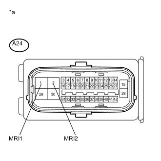
Text in Illustration *a Front view of wire harness connector
(to Skid Control ECU (Brake Booster with Master Cylinder Assembly))
Turn the power switch off.
-
Make sure that there is no looseness at the locking part and the connecting part of the connector.
-
Disconnect the A24 skid control ECU (brake booster with master cylinder assembly) connector.
-
Measure the voltage according to the value(s) in the table below.
Standard Voltage Tester Connection Condition Specified Condition A24-1 (MRI1) - Body ground Always 11 to 14 V A24-2 (MRI2) - Body ground Always 11 to 14 V
NG
REPAIR OR REPLACE HARNESS OR CONNECTOR (MRI CIRCUIT)
OK
-
-
CHECK HARNESS AND CONNECTOR (BRAKE BOOSTER WITH MASTER CYLINDER ASSEMBLY - BRAKE BOOSTER PUMP ASSEMBLY)
-
Make sure that there is no looseness at the locking part and the connecting part of the connectors.
-
Disconnect the A38, A39 and/or A67 brake booster pump assembly connectors.
-
Measure the resistance according to the value(s) in the table below.
Standard Resistance for LHD Tester Connection Condition Specified Condition A24-29 (MRO1) - A38-2 (BM1) Always Below 1 Ω A24-29 (MRO1) - Body ground Always 10 kΩ or higher A24-30 (MRO2) - A39-2 (BM2) Always Below 1 Ω A24-30 (MRO2) - Body ground Always 10 kΩ or higher for RHD Tester Connection Condition Specified Condition A24-29 (MRO1) - A67-1 (BM1) Always Below 1 Ω A24-29 (MRO1) - Body ground Always 10 kΩ or higher A24-30 (MRO2) - A39-2 (BM2) Always Below 1 Ω A24-30 (MRO2) - Body ground Always 10 kΩ or higher Result Result Proceed to OK (for LHD) A OK (for RHD) B NG C
A
REPLACE BRAKE BOOSTER WITH MASTER CYLINDER ASSEMBLY Click here
B
REPLACE BRAKE BOOSTER WITH MASTER CYLINDER ASSEMBLY Click here
C
REPAIR OR REPLACE HARNESS OR CONNECTOR
-
-
PERFORM ACTIVE TEST USING GTS (SOLENOID VALVE)
-
Select the Active Test on the GTS Click here.
Tech Tips
The Active Test can be performed when the following conditions are met.
-
ABS main relay is on.
-
Shift lever is in P.
-
Parking brake is applied.
-
Vehicle speed is 0 km/h (0 mph).
ABS/VSC/TRC Tester Display Test Part Control Range Diagnostic Note ECB* Solenoid (SMC/SRC/SCC) Switching solenoid valve (SMC/SRC/SCC) Solenoid ON/OFF Operation sound of solenoid (clicking sound) can be heard *: Electronically Controlled Brake System
-
-
Perform the Active Test of the solenoid using the GTS.
-
Select the Data List on the GTS Click here.
ABS/VSC/TRC Tester Display Measurement Item/Range Normal Condition Diagnostic Note Wheel Cylinder Pressure Sensor Wheel cylinder pressure sensor / Min.: 0.00 V, Max.: 5.00 V When brake pedal released: 0.10 to 0.90 V Reading increases when brake pedal is depressed -
Check that the output value of the wheel cylinder pressure sensor does not increase.
OK The output value of the wheel cylinder pressure sensor does not increase. Tech Tips
If the output value increases, there may be brake fluid leaks in the brake actuator.
Result Result Proceed to OK (for LHD) A OK (for RHD) B NG (for LHD) C NG (for RHD) D
A
REPLACE BRAKE BOOSTER PUMP ASSEMBLY Click here
B
REPLACE BRAKE BOOSTER PUMP ASSEMBLY Click here
C
REPLACE BRAKE BOOSTER WITH MASTER CYLINDER ASSEMBLY Click here
D
REPLACE BRAKE BOOSTER WITH MASTER CYLINDER ASSEMBLY Click here
-