ELECTRONICALLY CONTROLLED BRAKE SYSTEM, Diagnostic DTC:C1202/68

| DTC Code | DTC Name |
|---|---|
| C1202/68 | Master Reservoir Level Malfunction |
DESCRIPTION
When a fluid level drop in the brake master cylinder reservoir assembly is detected, a signal is sent to the skid control ECU (brake booster with master cylinder assembly).
If the DTC for the fluid level drop is memorized, the warning will be canceled and the DTC will not be stored when the fluid level returns to normal.
| DTC No. | INF Code | DTC Detection Condition | Trouble Area |
|---|---|---|---|
| C1202/68 | 371 | An open is detected in the switch signal circuit for 2 seconds or more. |
|
| ↑ | - | The reservoir level remains low. |
|
WIRING DIAGRAM
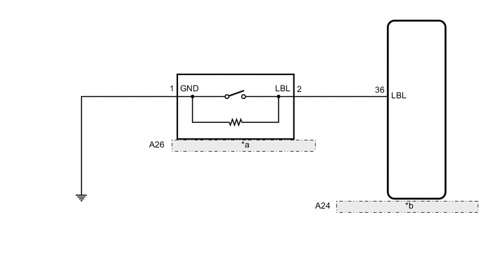
| *a | Brake Fluid Level Warning Switch (Brake Master Cylinder Reservoir Assembly) |
| *b | Skid Control ECU (Brake Booster with Master Cylinder Assembly) |
CAUTION / NOTICE / HINT
Note
Before replacing the skid control ECU (brake booster with master cylinder assembly), perform initialization and calibration of the linear solenoid valve Click here.
Tech Tips
Before releasing the parking brake, chock the wheels for safety.
PROCEDURE
-
CHECK BRAKE FLUID LEVEL
-
Check that the brake fluid level is sufficient.
OK Brake fluid level is sufficient. Tech Tips
If the fluid level is low, check for fluid leaks, and repair as necessary.
-
Check for brake fluid leaks (Connection between the brake booster pump assembly, brake master cylinder reservoir assembly and brake booster with master cylinder assembly, and the brake booster with master cylinder assembly and wheel cylinders).
Tech Tips
If no leaks exist, add and adjust fluid using the GTS Click here.
-
Check that the DTC is not output again Click here.
-
-
Check that there are no leaks from the connections between the brake booster pump assembly and brake booster with master cylinder assembly.
Tech Tips
As a visual check is very difficult, perform the check with the following procedure.
-
Bleed the air from the brake system Click here.
-
Connect the GTS to the DLC3.
-
Turn the power switch on (IG).
-
Select the Data List on the GTS Click here.
ABS/VSC/TRC Tester Display Measurement Item/Range Normal Condition Diagnostic Note Accumulator Sensor Accumulator pressure sensor / Min.: 0.00 V, Max.: 5.00 V Specified value: 2.90 to 4.20 V When brake fluid is stored in the accumulator: Accumulator pressure changes in accordance with volume of fluid stored in the accumulator -
Wait for 30 seconds without depressing the brake pedal.
-
Check that the accumulator pressure sensor output value change is within the specified range.
OK Accumulator pressure sensor output value change is less than 0.55 V.
-
NG 
CHECK AND REPAIR BRAKE FLUID LEAKS OR ADD FLUID
OK 
-
-
INSPECT BRAKE MASTER CYLINDER RESERVOIR ASSEMBLY
-
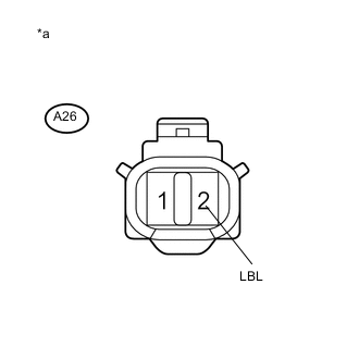
Text in Illustration *a Component without harness connected
(Brake Fluid Level Warning Switch (Brake Master Cylinder Reservoir Assembly))
Turn the power switch off.
-
Remove the reservoir filler cap.
-
Make sure that there is no looseness at the locking part and the connecting part of the connector.
-
Disconnect the A26 brake fluid level warning switch (brake master cylinder reservoir assembly) connector.
-
Measure the resistance according to the value(s) in the table below.
Tech Tips
A float is located inside the reservoir. Its position changes according to the level of brake fluid.
Standard Resistance Tester Connection Condition Specified Condition 2 (LBL) - 1 (GND) Brake fluid level warning switch OFF (Float up) 1.84 to 2.16 kΩ 2 (LBL) - 1 (GND) Brake fluid level warning switch ON (Float down) Below 1 Ω
NG
REPLACE BRAKE MASTER CYLINDER RESERVOIR ASSEMBLY Click here
OK
-
-
CHECK HARNESS AND CONNECTOR (BRAKE BOOSTER WITH MASTER CYLINDER ASSEMBLY - BRAKE MASTER CYLINDER RESERVOIR ASSEMBLY)
-
Make sure that there is no looseness at the locking part and the connecting part of the connector.
-
Disconnect the A24 skid control ECU (brake booster with master cylinder assembly) connector.
-
Measure the resistance according to the value(s) in the table below.
Standard Resistance Tester Connection Condition Specified Condition A24-36 (LBL) - A26-2 (LBL) Always Below 1 Ω A24-36 (LBL) - Body ground Always 10 kΩ or higher A26-1 (GND) - Body ground Always Below 1 Ω
NG
REPAIR OR REPLACE HARNESS OR CONNECTOR
OK
-
-
INSPECT BRAKE BOOSTER WITH MASTER CYLINDER ASSEMBLY (SWITCH INPUT)
-
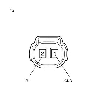
Text in Illustration *a Front view of wire harness connector
(to Brake Fluid Level Warning Switch (Brake Master Cylinder Reservoir Assembly))
Reconnect the A24 skid control ECU (brake booster with master cylinder assembly) connector.
-
Turn the power switch on (IG).
-
Measure the voltage according to the value(s) in the table below.
Standard Voltage Tester Connection Condition Specified Condition A26-2 (LBL) - Body ground Power switch on (IG) 11 to 14 V
NG
REPLACE BRAKE BOOSTER WITH MASTER CYLINDER ASSEMBLY Click here
OK
-
-
CHECK BRAKE DISC
-
Turn the power switch off.
-
Reconnect the A26 brake fluid level warning switch (brake master cylinder reservoir assembly) connector.
-
Disconnect the A34 brake pedal stroke sensor assembly connector.
-
Perform a road test according to Freeze Frame Data or customer problem analysis. While driving, check for abnormal brake pedal vibration caused by brake discs that are worn or have excess runout.
OK Brake pedal does not vibrate during braking. Tech Tips
-
An unevenly worn disc may vibrate the caliper pistons and cause fluctuations in brake line pressure, triggering a malfunction detection condition.
-
The brake pedal does not kick back due to caliper piston vibration during electronically controlled brake system control.
-
If the brake pedal stroke sensor assembly connector is disconnected, the fail-safe function will prohibit electronically controlled brake system control.
-
The Active Test does not prohibit electronically controlled brake system control when the vehicle is being driven, so disconnect the brake pedal stroke sensor assembly connector before continuing with inspection.
-
Uneven disc wear can be checked by measuring the disc thickness variation (See page for front, or Click here for rear).
-
NG
REPLACE BRAKE DISC
OK
-
-
RECONFIRM DTC
-
Reconnect the A34 brake pedal stroke sensor assembly connector.
-
Clear the DTCs Click here.
-
Turn the power switch on (READY).
-
Perform a road test.
-
Check if the same DTC is output Click here.
Result Result Proceed to DTC C1202/68 is not output. A DTC C1202/68 is output. B Tech Tips
If troubleshooting has been carried out according to Problem Symptoms Table, refer back to the table and proceed to the next step Click here.
A
USE SIMULATION METHOD TO CHECK Click here
B
REPLACE BRAKE BOOSTER WITH MASTER CYLINDER ASSEMBLY Click here
-