ELECTRONICALLY CONTROLLED BRAKE SYSTEM, Diagnostic DTC:C1231/31

| DTC Code | DTC Name |
|---|---|
| C1231/31 | Steering Angle Sensor Circuit Malfunction |
DESCRIPTION
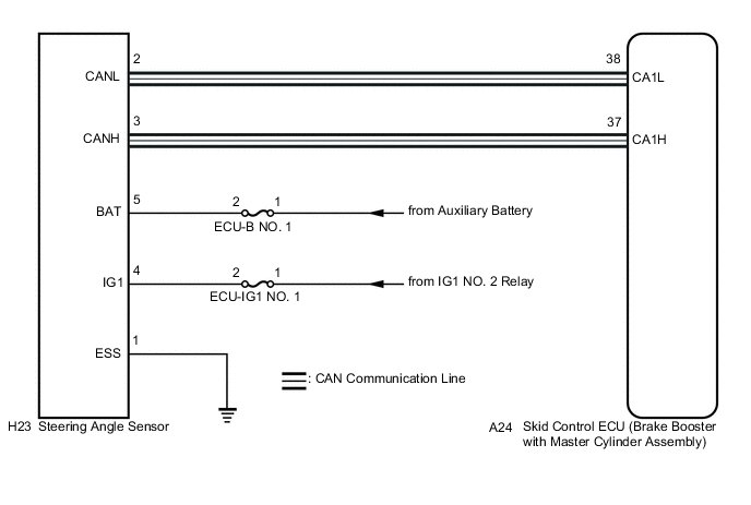
The skid control ECU (brake booster with master cylinder assembly) receives steering angle sensor signals via the CAN communication system. When a malfunction occurs in the communication line with the steering angle sensor, DTC U0126/63 (Lost Communication with Steering Angle Sensor Module) is stored.
| DTC No. | INF Code | DTC Detection Condition | Trouble Area |
|---|---|---|---|
| C1231/31 | 701 | While steering angle sensor communication is enabled, a malfunction signal output is received during the sensor self-check (sensor malfunction). | Steering angle sensor internal malfunction |
| ↑ | 702 | While steering angle sensor communication is enabled, a malfunction signal output is received during the sensor self-check (internal malfunction). | ↑ |
| ↑ | 703 | While steering angle sensor communication is enabled, a malfunction signal output is received during the sensor self-check (+B malfunction). | ↑ |
WIRING DIAGRAM
CAUTION / NOTICE / HINT
Note
Inspect the fuses for circuits related to this system before performing the following inspection procedure.
Tech Tips
-
When U0126/63 is output together with C1231/31, inspect and repair the trouble areas indicated by U0126/63 first Click here.
-
When a speed sensor or yaw rate and acceleration sensor (airbag sensor assembly) is malfunctioning, DTCs for the steering angle sensor may be output even when the steering angle sensor is normal. When DTCs for a speed sensor or yaw rate and acceleration sensor (airbag sensor assembly) are output together with DTCs for the steering angle sensor, inspect and repair the speed sensor and yaw rate and acceleration sensor (airbag sensor assembly) first, and then inspect and repair the steering angle sensor.
PROCEDURE
-
CHECK DTC
-
Clear the DTCs Click here.
-
Turn the power switch off.
-
Turn the power switch on (IG) again and check that no CAN communication system DTCs are output Click here.
-
Drive the vehicle at a speed of 35 km/h (22 mph), turn the steering wheel to the right and left, and check that no speed sensor and/or yaw rate and acceleration sensor DTCs are output Click here.
Result Result Proceed to DTC C1231/31 is output. A CAN communication system DTCs are output. B Speed sensor and/or yaw rate and acceleration sensor DTCs are output. C DTC C1231/31 is not output. D Tech Tips
-
When DTCs indicating CAN communication system malfunctions are output, repair the CAN communication system before repairing each corresponding sensor.
-
If there is a malfunction in the speed sensor or yaw rate and acceleration sensor (airbag sensor assembly), an abnormal value may be output even though the steering angle sensor is normal.
-
If speed sensor and yaw rate and acceleration sensor DTCs are output simultaneously, repair the sensors and inspect the steering angle sensor.
-
B 
INSPECT CAN COMMUNICATION SYSTEM Click here
C
REPAIR CIRCUITS INDICATED BY OUTPUT DTCS Click here
D
USE SIMULATION METHOD TO CHECK Click here
A 
-
-
CHECK HARNESS AND CONNECTOR (POWER SOURCE TERMINAL)
-
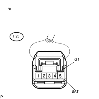
Text in Illustration *a Front view of wire harness connector
(to Steering Angle Sensor)
Turn the power switch off.
-
Remove the steering wheel and the column cover.
-
Make sure that there is no looseness at the locking part and the connecting part of the connector.
-
Disconnect the H23 steering angle sensor connector.
-
Measure the voltage according to the value(s) in the table below.
Standard Voltage Tester Connection Condition Specified Condition H23-4 (IG1) - Body ground Power switch on (IG) 11 to 14 V H23-5 (BAT) - Body ground Always 11 to 14 V
NG
REPAIR OR REPLACE HARNESS OR CONNECTOR (POWER SOURCE CIRCUIT)
OK
-
-
CHECK HARNESS AND CONNECTOR (GROUND TERMINAL)
-
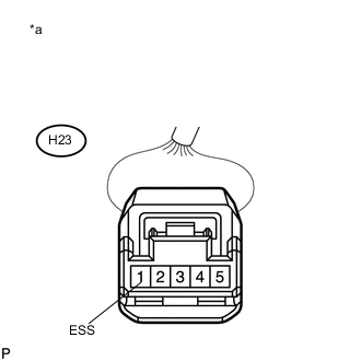
Text in Illustration *a Front view of wire harness connector
(to Steering Angle Sensor)
Turn the power switch off.
-
Measure the resistance according to the value(s) in the table below.
Standard Resistance Tester Connection Condition Specified Condition H23-1 (ESS) - Body ground Always Below 1 Ω Tech Tips
If troubleshooting has been carried out according to Problem Symptoms Table, refer back to the table and proceed to the next step Click here.
OK
REPLACE STEERING ANGLE SENSOR Click here
NG
REPAIR OR REPLACE HARNESS OR CONNECTOR (GROUND CIRCUIT)
-