| DTC Code | DTC Name |
|---|---|
| B1247 | Tire Pressure Monitor Receiver Communication Stop |
DESCRIPTION
The main body ECU (multiplex network body ECU) and tire pressure warning ECU and receiver are connected using 2 direct lines that they use to communicate with each other.
| DTC No. | DTC Detection Condition | Trouble Area |
|---|---|---|
| B1247 | In diagnostic mode, an applicable RDA signal cannot be received within 10 seconds after a PRG signal is sent from the main body ECU (multiplex network body ECU). |
|
CAUTION / NOTICE / HINT
-
When replacing the tire pressure warning ECU and receiver, read the transmitter IDs stored in the old ECU using the GTS and write them down before removal.
-
It is necessary to perform initialization (See page ) after registration (Click here) of the transmitter IDs into the tire pressure warning ECU and receiver after the ECU has been replaced.
-
If the main body ECU (multiplex network body ECU) is replaced, refer to Service Bulletin.
Inspect the fuses for circuits related to this system before performing the following inspection procedure.
PROCEDURE
- Click here
CHECK HARNESS AND CONNECTOR (MAIN BODY ECU (MULTIPLEX NETWORK BODY ECU) - TIRE PRESSURE WARNING ECU AND RECEIVER)
-
Disconnect the P29 or P25 tire pressure warning ECU and receiver connector.
-
Disconnect the H10 main body ECU (multiplex network body ECU) connector.
-
Measure the resistance according to the value(s) in the table below.
Standard Resistance Table 1. for FMVSS138 Type Tester Connection Condition Specified Condition P29-4 (RDA) - H10-16 (RDA) Always Below 1 Ω H10-16 (RDA) - Body ground Always 10 kΩ or higher Table 2. for ECE-R64 Type Tester Connection Condition Specified Condition P25-4 (RDA2) - H10-16 (RDA) Always Below 1 Ω H10-16 (RDA) - Body ground Always 10 kΩ or higher
- OKClick here
- NG
REPAIR OR REPLACE HARNESS OR CONNECTOR
-
- Click here
CHECK HARNESS AND CONNECTOR (POWER SOURCE OF TIRE PRESSURE WARNING ECU AND RECEIVER)
-
Measure the resistance according to the value(s) in the table below.
Standard Resistance Table 3. for FMVSS138 Type Tester Connection Condition Specified Condition P29-12 (GND) - Body ground Always Below 1 Ω Table 4. for ECE-R64 Type Tester Connection Condition Specified Condition P25-12 (GND) - Body ground Always Below 1 Ω -
Measure the voltage according to the value(s) in the table below.
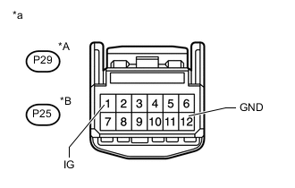
Standard Voltage Table 5. for FMVSS138 Type Tester Connection Condition Specified Condition P29-1 (IG) - Body ground Power switch on (IG) 10 to 16 V Table 6. for ECE-R64 Type Tester Connection Condition Specified Condition P25-1 (IG) - Body ground Power switch on (IG) 10 to 16 V Table 7. Text in Illustration *A for FMVSS138 Type *B for ECE-R64 Type *a Front view of wire harness connector
(to Tire Pressure Warning ECU and Receiver)
- OKClick here
- NG
REPAIR OR REPLACE HARNESS OR CONNECTOR
-
- Click here
REPLACE TIRE PRESSURE WARNING ECU AND RECEIVER
-
Replace the tire pressure warning ECU and receiver (Click here).
- NEXTClick here
-
- Click here
CHECK DTC OUTPUT (B1247)
-
Clear the DTCs (Click here).
-
Turn the power switch off.
-
Turn the power switch on (IG).
-
Check for DTCs (Click here).
OK DTC B1247 is not output.
- OK
END
- NG
REPLACE MAIN BODY ECU (MULTIPLEX NETWORK BODY ECU) (Click here)
-