Info Added 2017-08-02
PROCEDURE
- Click here
INSTALL HOLE PLUG
-
Install the 4 hole plugs to the rear suspension member sub-assembly.
-
- Click here
INSTALL REAR SUSPENSION MEMBER BODY MOUNTING FRONT CUSHION LH
-
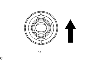
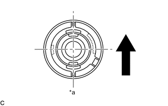
Temporarily install a new rear suspension member body mounting front cushion LH to the position shown in the illustration.
Table 1. Text in Illustration *a View from beneath 
Front of the Vehicle -
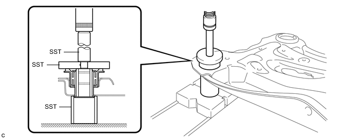
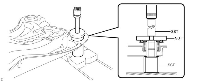
Using SST and a press, install the rear suspension member body mounting front cushion LH to the rear suspension member sub-assembly.
09710-30012 09710-04061 09950-60010 09951-00650 09950-70010 09951-07100 Tip:Slowly press in the rear suspension member body mounting front cushion LH.
-
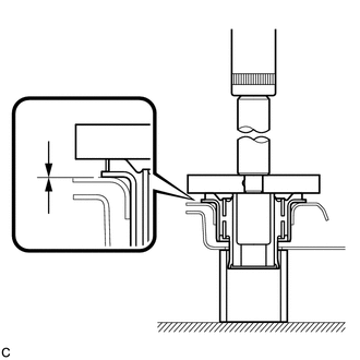
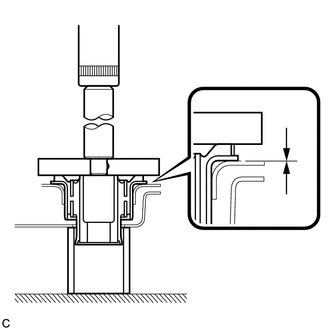
While observing from the side, press in the rear suspension member body mounting front cushion LH until there is no clearance between the rear suspension member body mounting front cushion LH and the rear suspension member sub-assembly as shown in the illustration.
Note:Do not press the rear suspension member excessively, or it will easily deform.
-
- Click here
INSTALL REAR SUSPENSION MEMBER BODY MOUNTING FRONT CUSHION RH
-

Temporarily install a new rear suspension member body mounting front cushion RH to the position shown in the illustration.
Table 2. Text in Illustration *a View from beneath Front of the Vehicle -
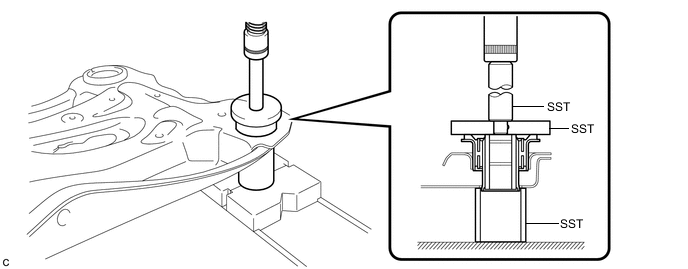
Using SST and a press, install the rear suspension member body mounting front cushion RH to the rear suspension member sub-assembly.
09710-30012 09710-04061 09950-60010 09951-00650 09950-70010 09951-07100 Tip:Slowly press in the rear suspension member body mounting front cushion RH.
-

While observing from the side, press in the rear suspension member body mounting front cushion RH until there is no clearance between the rear suspension member body mounting front cushion RH and the rear suspension member sub-assembly as shown in the illustration.
Note:Do not press the rear suspension member excessively, or it will easily deform.
-
- Click here
INSTALL REAR SUSPENSION MEMBER BODY MOUNTING REAR CUSHION (for LH Side)
-
Temporarily install a new rear suspension member body mounting rear cushion (LH side) to the position shown in the illustration.
Table 3. Text in Illustration *a View from beneath Front of the Vehicle -
Using SST and a press, install the rear suspension member body mounting rear cushion (LH side) to the rear suspension member sub-assembly.
09710-30012 09710-04061 09950-60010 09951-00650 09950-70010 09951-07100 Tip:Slowly press in the rear suspension member body mounting rear cushion.
-
While observing from the side, press in the rear suspension member body mounting rear cushion (LH side) until there is no clearance between the rear suspension member body mounting rear cushion (LH side) and the rear suspension member sub-assembly as shown in the illustration.
Note:Do not press the rear suspension member excessively, or it will easily deform.
-
- Click here
INSTALL REAR SUSPENSION MEMBER BODY MOUNTING REAR CUSHION (for RH Side)
Tip:Perform the same procedure as the LH side.
- Click here
INSTALL REAR SUSPENSION MEMBER SUB-ASSEMBLY
-

Support the rear suspension member sub-assembly with an engine lifter using 4 attachments or equivalent tools.
Table 4. Text in Illustration *1 Engine Lifter *2 Attachment 
Attachment Placement Location Note:
-
Make sure to secure the rear suspension member sub-assembly to prevent it from dropping.
-
Use the attachments to keep the rear suspension member sub-assembly level.
-
-
Raise the rear suspension member sub-assembly until there is no clearance between the rear suspension member sub-assembly and the vehicle body.
Note:When raising the rear suspension member sub-assembly, be careful not to damage the vehicle body or other components installed on the vehicle.
-
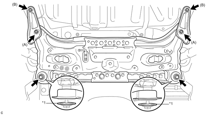
Install the rear suspension member sub-assembly, rear suspension member lower stopper sub-assembly LH and rear suspension member lower stopper sub-assembly RH with the 4 nuts.
Table 5. Text in Illustration *1 Rear Suspension Member Lower Stopper - - Nut A 55 N*m 561 kgf*cm 41 ft.*lbf Nut B 38 N*m 387 kgf*cm 28 ft.*lbf -
Install the 2 rear suspension member lower stoppers with the 2 bolts to the rear suspension member sub-assembly.
56 N*m 566 kgf*cm 41 ft.*lbf Note:Be sure to install the rear suspension member sub-assembly with the rear suspension member lower stoppers in the correct direction, as shown in the illustration.
-
- Click here
TEMPORARILY TIGHTEN REAR NO. 1 SUSPENSION ARM ASSEMBLY LH
- Click here
TEMPORARILY TIGHTEN REAR NO. 1 SUSPENSION ARM ASSEMBLY RH
Tip:Perform the same procedure as the LH side.
- Click here
TEMPORARILY TIGHTEN REAR NO. 2 SUSPENSION ARM ASSEMBLY LH
- Click here
TEMPORARILY TIGHTEN REAR NO. 2 SUSPENSION ARM ASSEMBLY RH
Tip:Perform the same procedure as the LH side.
- Click here
INSTALL NO. 3 EXHAUST PIPE SUPPORT BRACKET
-
Install the No. 3 exhaust pipe support bracket to the rear suspension member sub-assembly with the 2 bolts.
33 N*m 337 kgf*cm 24 ft.*lbf
-
- Click here
CONNECT REAR NO. 1 SUSPENSION ARM ASSEMBLY LH
- Click here
CONNECT REAR NO. 1 SUSPENSION ARM ASSEMBLY RH
Tip:Perform the same procedure as the LH side.
- Click here
CONNECT REAR NO. 2 SUSPENSION ARM ASSEMBLY LH
- Click here
CONNECT REAR NO. 2 SUSPENSION ARM ASSEMBLY RH
Tip:Perform the same procedure as the LH side.
- Click here
STABILIZE SUSPENSION
- Click here
FULLY TIGHTEN REAR NO. 1 SUSPENSION ARM ASSEMBLY LH
- Click here
FULLY TIGHTEN REAR NO. 1 SUSPENSION ARM ASSEMBLY RH
Tip:Perform the same procedure as the LH side.
- Click here
FULLY TIGHTEN REAR NO. 2 SUSPENSION ARM ASSEMBLY LH
- Click here
FULLY TIGHTEN REAR NO. 2 SUSPENSION ARM ASSEMBLY RH
Tip:Perform the same procedure as the LH side.
- Click here
INSTALL REAR HEIGHT CONTROL SENSOR SUB-ASSEMBLY
- Click here
INSTALL REAR STABILIZER BAR
- Click here
CONNECT REAR STABILIZER LINK ASSEMBLY LH
-
Connect the rear stabilizer link assembly LH to the rear stabilizer bar with nut.
39 N*m 400 kgf*cm 29 ft.*lbf If the ball joint turns together with the nut, use a hexagon wrench to hold the stud.
-
- Click here
CONNECT REAR STABILIZER LINK ASSEMBLY RH
Tip:Perform the same procedure as the LH side.
- Click here
INSTALL CENTER EXHAUST PIPE ASSEMBLY
- Click here
INSTALL NO. 2 FLOOR UNDER COVER
- Click here
INSTALL NO. 1 FLOOR UNDER COVER
- Click here
INSTALL REAR WHEELS
103 N*m 1049 kgf*cm 76 ft.*lbf - Click here
INSPECT AND ADJUST REAR WHEEL ALIGNMENT