AIR CONDITIONING SYSTEM, Diagnostic DTC:B1461/61
| DTC Code | DTC Name |
|---|---|
| B1461/61 | Emission Gas NOx Sensor Circuit |
DESCRIPTION
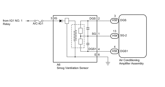
The smog ventilation sensor is installed to the front of the cooler condenser assembly and is used to control automatic switching between RECIRCULATION and FRESH modes. The smog ventilation sensor detects components of the exhaust gasses (NOx) and transmits a signal to the air conditioning amplifier assembly.
| DTC Code | DTC Detection Condition | Trouble Area |
|---|---|---|
| B1461/61 | Short in smog ventilation sensor circuit (NOx) |
|
WIRING DIAGRAM
CAUTION / NOTICE / HINT
Note
-
Inspect the fuses for circuits related to this system before performing the following inspection procedure.
-
If DTCs B1418/18 and B1461/61 are stored simultaneously, there may be a malfunction in the smog ventilation sensor power source related circuits.
PROCEDURE
-
READ VALUE USING GTS
-
Connect the GTS to the DLC3.
-
Turn the power switch on (IG).
-
Turn the GTS on.
-
Enter the following menus: Body Electrical / Air Conditioner / Data List.
-
Check the value(s) by referring to the table below.
Air Conditioner Tester Display Measurement Item/Range Normal Condition Diagnostic Note Emission Gas Nox Sensor Emission gas (NOx) /
Min.: 0, Max.: 255
Smog ventilation sensor value increases as gas amount increases - OK The display is as specified in the Normal Condition column. Result Result Proceed to NG A OK (When troubleshooting according to Problem Symptoms Table) B OK (When troubleshooting according to the DTC) C
B 
PROCEED TO NEXT SUSPECTED AREA SHOWN IN PROBLEM SYMPTOMS TABLE Click here
C
REPLACE AIR CONDITIONING AMPLIFIER ASSEMBLY Click here
A 
-
-
CHECK HARNESS AND CONNECTOR (SMOG VENTILATION SENSOR - IG POWER SOURCE AND BODY GROUND)
-
Disconnect the A6 smog ventilation sensor connector.
-
Measure the voltage according to the value(s) in the table below.
Standard Voltage Tester Connection Condition Specified Condition A6-3 (IG) - Body ground Power switch on (IG) 11 to 14 V A6-3 (IG) - Body ground Power switch off Below 1 V -
Measure the resistance according to the value(s) in the table below.
Standard Resistance Tester Connection Condition Specified Condition A6-6 (E) - Body ground Always Below 1 Ω
NG
REPAIR OR REPLACE HARNESS OR CONNECTOR
OK
-
-
CHECK HARNESS AND CONNECTOR (SMOG VENTILATION SENSOR - AIR CONDITIONING AMPLIFIER ASSEMBLY)
-
Disconnect the H54 and H55 air conditioning amplifier assembly connectors.
-
Measure the resistance according to the value(s) in the table below.
Standard Resistance Tester Connection Condition Specified Condition A6-1 (SG) - H54-13 (SG-2) Always Below 1 Ω A6-4 (DGS1) - H55-4 (DGS1) Always Below 1 Ω A6-1 (SG) - Body ground Always 10 kΩ or higher A6-4 (DGS1) - Body ground Always 10 kΩ or higher
NG
REPAIR OR REPLACE HARNESS OR CONNECTOR
OK
-
-
INSPECT SMOG VENTILATION SENSOR
-
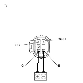
Text in Illustration *a Component without harness connected
(Smog Ventilation Sensor)
Connect a auxiliary battery positive (+) lead to terminal 3 (IG) and a negative (-) lead to terminal 6 (E).
-
Allow exhaust gas (NOx) to travel to the sensing portion of the smog ventilation sensor, and measure the resistance between terminals 1 (SG) and 4 (DGS1).
OK When the sensor is exposed to the exhaust gas, the resistance increases. Tech Tips
The resistance of the sensor before being exposed to exhaust gas is 10 kΩ to 40 kΩ.
OK
REPLACE AIR CONDITIONING AMPLIFIER ASSEMBLY Click here
NG
REPLACE SMOG VENTILATION SENSOR Click here
-