Click here
-
GENERAL
-
The air conditioning system has the following controls.
Control Outline Neural Network Control This control is capable of performing complex control by artificially simulating the information processing method of the nervous system of living organisms in order to establish a complex input/output relationship similar to that of a human brain. Automatic Recirculation Control Automatically changes the air inlet mode to FRESH or RECIRCULATION mode according to the level of harmful elements (CO, HC and NOx) in the outside air, cabin temperature, and outside temperature. Outlet Air Temperature Control Based on the temperature set by the temperature control switch, neural network control calculates outlet air temperature based on input signals from various sensors. Dual Control*1 The temperature settings for the driver and front passenger are controlled independently in order to provide separate vehicle interior temperatures for the right and left sides of the vehicle. Thus, air conditioning that accommodates the occupants' preferences has been realized. 3 Zone Control*2 The temperature setting for the driver, front passenger and rear passengers is controlled independently in order to provide a 3 zone vehicle interior temperature for the driver, front passenger and rear seat. Thus, air conditioning control that accommodates occupants preferences has been realized. Blower Control Controls the blower motor with fan sub-assembly in accordance with the airflow volume that has been calculated by neural network control based on the input signals from various sensors. Air Outlet Control Automatically switches the air outlets in accordance with the outlet mode that has been calculated by neural network control. In accordance with the engine coolant temperature, ambient air temperature, amount of sunlight, required blower, outlet temperature and vehicle speed conditions, this control automatically switches the blower outlet to foot and defroster mode to prevent the windows from becoming fogged up when the ambient air temperature is low. Air Inlet Control Automatically controls the air inlet control damper to help achieve the calculated outlet air temperature that is required. Drives the air inlet control servo motor according to the operation of the air inlet control switch and moves the dampers to the fresh or recirculation position. Electric Inverter Compressor Control The air conditioning amplifier assembly calculates the target speed of the compressor based on the target evaporator temperature (which is calculated by the room temperature sensor, outside temperature sensor, solar sensor (automatic light control sensor)) and the actual evaporator temperature that is detected by the evaporator temperature sensor in order to control the compressor speed. The air conditioning amplifier assembly calculates the target evaporator temperature, which includes corrections based on the room temperature sensor, outside temperature sensor, the solar sensor (automatic light control sensor), and evaporator temperature sensor. Accordingly, the air conditioning amplifier assembly controls the compressor speed to an extent that would not inhibit the proper cooling performance or defogging performance. Turns the A/C on automatically when the AUTO button is pressed when the blower is on and the A/C is off. Decreases the compressor speed in order to ensure quietness when the vehicle is stopped or the engine is off. Pollen Removal Mode Control
-
Activated by the pollen removal mode switch operation.
-
Switches the air vent to FACE mode.
-
Sends air which has passed through the clean air filter to the area around the upper part of the bodies of the driver and front passenger. This air is filtered by the clean air filter in order to remove pollen.
Defroster Control Defroster control logic is used to improve defroster performance. PTC Heater Control When the hybrid system is operating (READY), and the blower motor with fan sub-assembly is turned on, the air conditioning amplifier assembly turns on the PTC heater assembly (quick heater assembly) if the conditions listed below are met.
- Engine coolant temperature is below specified temperature.
- Outside temperature is below specified temperature.
- Tentative air mix damper opening angle is above the specified value (MAX HOT).
Rear Defogger Control When the power switch is on (IG) and the rear defogger switch is pushed, the system is activated to keep the defogger heater on for approximately 15 minutes. ECO Mode Control When the ECO mode switch (integration control and panel assembly) is turned on, the air conditioning amplifier assembly limits the air conditioning system performance. Diagnosis A Diagnostic Trouble Code (DTC) is stored in memory when the air conditioning amplifier assembly detects a problem with the air conditioning system.
-
*1: for Dual Type
-
*2: for 3 Zone Type
-
-
-
NEURAL NETWORK CONTROL
-
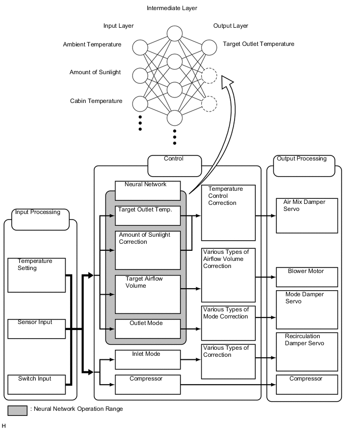
In previous automatic air conditioning systems, the air conditioning amplifier assembly determined the required outlet air temperature and blower air volume in accordance with the calculation formula that has been obtained based on information received from the sensors.
However, because the senses of a person are rather complex, a given temperature is sensed differently, depending on the environment in which the person is situated. For example, a given amount of solar radiation can feel comfortably warm in a cold climate, or extremely uncomfortable in a hot climate. Therefore, as a technique for effecting a higher level of control, a neural network has been adopted in the automatic air conditioning system. With this technique, the data that has been collected under varying environmental conditions is stored in the air conditioning amplifier assembly. The air conditioning amplifier assembly can then effect control to provide enhanced air conditioning comfort.
-
The neural network control consists of neurons in the input layer, intermediate layer and output layer. The input layer neurons process the input data of the outside temperature, the amount of sunlight and the room temperature based on the outputs of the switches and sensors, and outputs it to the intermediate layer neurons. Based on this data, the intermediate layer neurons adjust the strength of the links among the neurons. The sum of these is then calculated by the output layer neurons in the form of the required outlet temperature, solar correction, target airflow volume and outlet mode control volume. Accordingly, the air conditioning amplifier assembly controls the servo motors and blower motor in accordance with the control volumes that have been calculated by the neural network control.
-
-
MODE POSITION AND DAMPER OPERATION
-
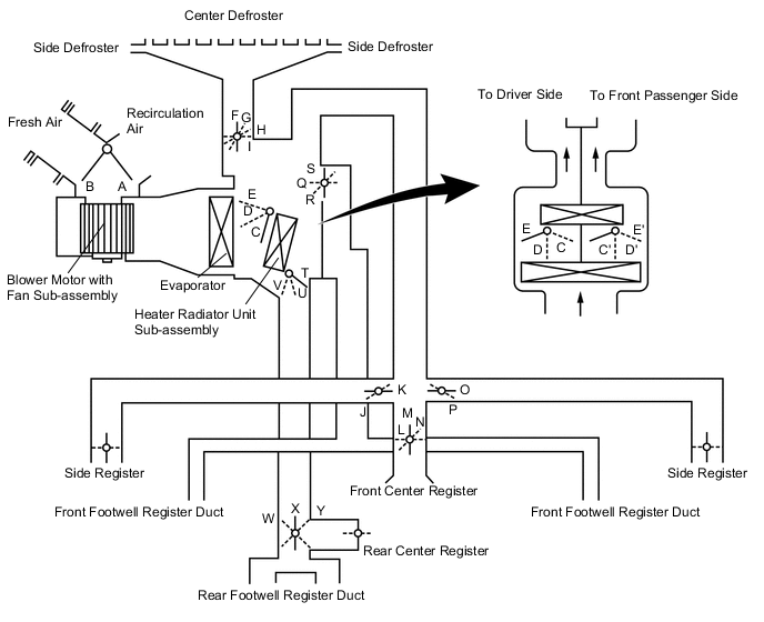
Mode Position and Damper Operation
Table 1. Functions of Main Dampers Control Damper Operation Position Damper Position Operation Air Inlet Control Damper FRESH A Allows fresh air to enter. RECIRCULATION B Causes internal air to recirculate. Air Mix Control Damper MAX COLD to MAX HOT Temperature Setting C - D - E
(C' - D' - E')
T - U - V
Varies the mixture ratio of warm air and cool air in order to regulate the temperature continuously between hot and cold. Air Outlet Control Damper DEF

F, J, L, P, S, Y Defrosts the windshield through the center defroster, side defrosters, and side registers. FOOT / DEF

G, J, L, P, Q, X Defrosts the windshield through the center defroster, side defrosters, side registers, and rear center register, while air is also blown out from the front and rear footwell register ducts. FOOT

H, J, L, P, Q, X Air blows out of the front and rear footwell register duct, rear center registers, and side registers. In addition, air blows out slightly from the center defroster and side defrosters. BI-LEVEL

I, K, N, O, R, X Air blows out of the front and rear center registers, side registers and front and rear footwell registers ducts. FACE

I, K, M, O, S, W Air blows out of the front and rear center registers, and side registers.
-
-
AIR OUTLETS AND AIRFLOW VOLUME
-
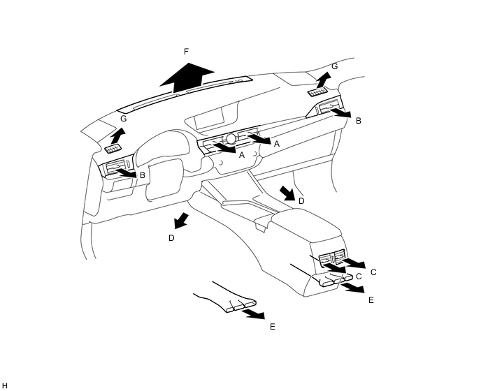
Air Outlets and Airflow Volume
MODE Selection Register Footwell Defroster Automatic Manual CTR SIDE RR FR RR CTR SIDE A B C D E F G FACE-U*1 


B/L-U*2 

FOOT-F*3 
FOOT-R*4 FOOT-D*5 F/D DEF 
-
*1: Air blows out of registers only
-
*2: Regular bi-level mode
-
*3: Regular foot mode
-
*4: Foot mode with large airflow volume from the rear footwell register ducts.
-
*5: Foot mode with large airflow volume from the defrosters
-
The size of each circle ○ indicates the ratio of airflow volume.
-
-
-
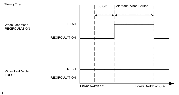
PARKING FRESH CONTROL
When the vehicle is parked, the air conditioning unit uses control logic which automatically changes the air inlet to FRESH mode to purge undesired odors from the air conditioning unit.
This logic will therefore reduce undesired odors upon starting the air conditioning system.
-
COMPRESSOR WITH MOTOR ASSEMBLY
-
General
Tip:In order to ensure the proper insulation of the internal high-voltage portion of the compressor and the compressor housing, this vehicle has adopted a compressor oil (ND-OIL 11) with a high level of insulation performance. Therefore, never use a compressor oil other than ND-OIL 11 type compressor oil or its equivalent.
-
Along with the use of the hybrid system on this vehicle, an electric inverter compressor that is driven by a motor is used. The basic construction and operation of this compressor are the same as an ordinary scroll compressor, except that it is driven by an electric motor.
-
The Air Conditioning (A/C) inverter is integrated with the compressor.
-
The electric motor is actuated by 3-phase alternating current (244.8 V) supplied by the A/C inverter. As a result, the air conditioning control system on this vehicle is actuated without depending on the operation of the engine, thus realizing a comfortable air conditioning system and low fuel consumption.
-
Due to the use of an electric inverter compressor, the compressor speed can be controlled at the required speed calculated by the air conditioning amplifier assembly. Thus, the cooling and dehumidification performance and power consumption have been optimized.
-
Low-moisture permeation hoses are used for the suction and discharge hoses at the compressor in order to minimize the entry of moisture into the refrigeration cycle.
-
The compressor uses high-voltage alternating current. If a short or open circuit occurs in the compressor, the power management control ECU will cut off the A/C inverter circuit in order to stop the power supply to the compressor motor.
-
-
Compressor Speed Control
-
The air conditioning amplifier assembly calculates the target compressor speed based on the target evaporator temperature (calculated from the temperature control switch, room temperature sensor, ambient temperature sensor, and solar sensor (automatic light control sensor)) and the actual evaporator temperature detected by the evaporator temperature sensor. Then, the air conditioning amplifier assembly transmits the target speed to the power management control ECU. The power management control ECU controls the A/C inverter based on the target speed data in order to control the compressor to a speed that suits the operating condition of the air conditioning system.
-
The air conditioning amplifier assembly calculates the target evaporator temperature, which includes corrections based on the room temperature sensor, outside temperature sensor, solar sensor (automatic light control sensor), and evaporator temperature sensor. Accordingly, the air conditioning amplifier assembly controls the compressor speed to an extent that does not inhibit proper cooling performance or defogging performance. As a result, comfort and low fuel consumption can be realized.
-
-
-
AUTOMATIC RECIRCULATION CONTROL
-
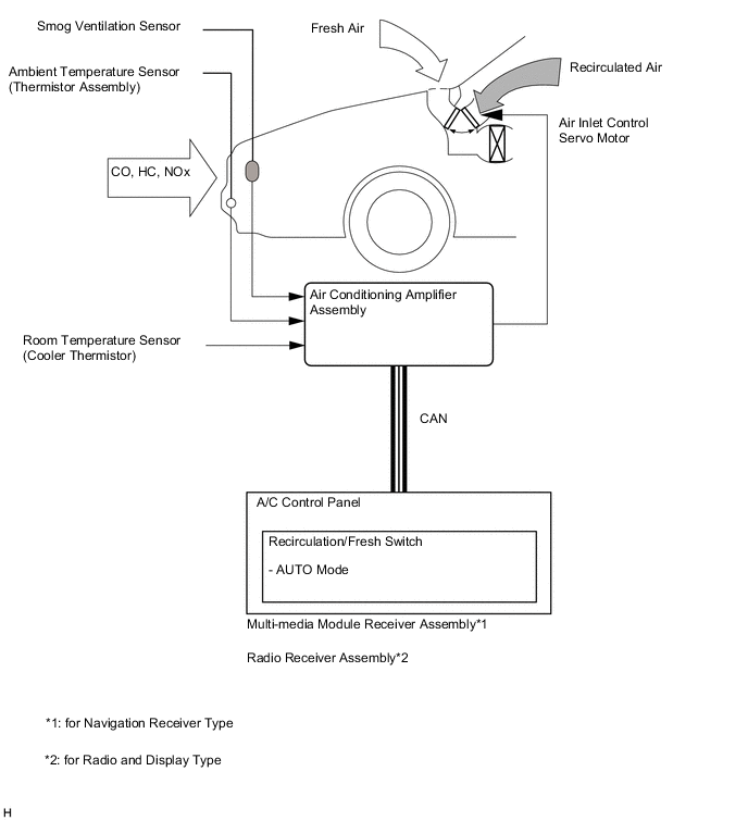
When automatic recirculation control is operating, the air conditioning amplifier assembly automatically changes the air inlet mode to FRESH or RECIRCULATION mode based on signals from the smog ventilation sensor, ambient temperature sensor (thermistor assembly) and room temperature sensor (cooler (room temp. sensor) thermistor) when AUTO mode is selected.
-
The air conditioning amplifier assembly detects harmful elements (CO, HC and NOx) based on a smog ventilation sensor signal and automatically switches the air inlet mode to RECIRCULATION mode to prevent such harmful elements (CO, HC and NOx) from entering the cabin.
-
The air conditioning amplifier assembly detects cabin temperature based on a room temperature sensor signal and automatically switches the air inlet mode to RECIRCULATION mode to prevent the cabin temperature from becoming too high.
-
The air conditioning amplifier assembly detects the outside temperature based on an ambient temperature sensor signal and automatically switches the air inlet mode to FRESH mode to prevent the windshield from fogging up.
Note:The smog ventilation sensor cannot detect elements such as the smoke from a bonfire or factory exhaust, foul or animal odors, and dirt or dust particles. Therefore, the air inlet mode is not switched automatically in accordance with those elements.
-
-
-
ION GENERATOR
-
The No. 1 ion generator sub-assembly is controlled by the air conditioning assembly and operates in accordance with the blower motor with fan sub-assembly.
-
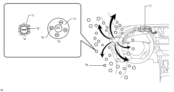
The No. 1 ion generator sub-assembly emits "nanoe" ions that are electrically charged and encapsulated with water. The ions are discharged into the cabin through the side register (driver side) to provide skin-friendly clean air.*1
CAUTION:Do not attempt to disassemble or repair the No. 1 ion generator sub-assembly because it contains high voltage parts.
Note:Do not insert anything into the side register (driver side), attach anything to it, or use sprays around it. These things may cause the No. 1 ion generator sub-assembly to not work properly.
Tip:
-
*1: According to the temperature and humidity conditions, fan speed and air outlet mode selected, the No. 1 ion generator sub-assembly may not operate at full capacity.
-
When the No. 1 ion generator sub-assembly operates, a small amount of ozone is emitted and may be faintly smelled in some situations. However, this is approximately the same as the amount that already exists in nature, such as in forests, and as such has no effect on the human body.
-
A slight noise may be heard during operation. This does not indicate a malfunction.
-
Table 2. Text in Illustration *1 No. 1 Ion Generator Sub-assembly - - *a Common Negative Ion *b "nanoe" Ion *c H2O
*d Electron Tip:"nanoe" is a trademark of Panasonic Co., Ltd.
-
-
EVAPORATOR TEMPERATURE SENSOR (NO. 1 COOLER THERMISTOR)
The evaporator temperature sensor (No. 1 cooler thermistor) detects the temperature of the cool air immediately after the evaporator in the form of resistance changes, and outputs it to the air conditioning amplifier assembly.
-
BLOWER MOTOR WITH FAN SUB-ASSEMBLY
The blower motor with fan sub-assembly has a built-in blower controller, and is controlled using duty control performed by the air conditioning amplifier assembly.
-
POLLEN REMOVAL MODE CONTROL
-
When the pollen removal mode switch is pressed, pollen removal mode control is activated.
-
Then, the air vent is switched to FACE mode and recirculated pollen-free air flows in the area around the upper part of the bodies of the driver and front passenger.
-
When the pollen removal mode switch signal is input to the air conditioning amplifier assembly, the air conditioning amplifier assembly controls the compressor with motor assembly, air inlet control servo motor, air outlet control servo motor and blower motor as shown in the timing chart below.
-
This control usually operates for approximately 3 minutes. However, when the outside temperature is low (5°C (41°F) maximum), it will operate for approximately 1 minute.
-
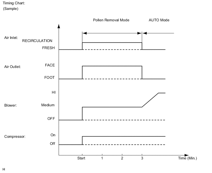
After this control stops operating, the air conditioning amplifier assembly controls the air conditioning system using AUTO mode.
-
-
BUS CONNECTOR (AIR CONDITIONING HARNESS ASSEMBLY)
-
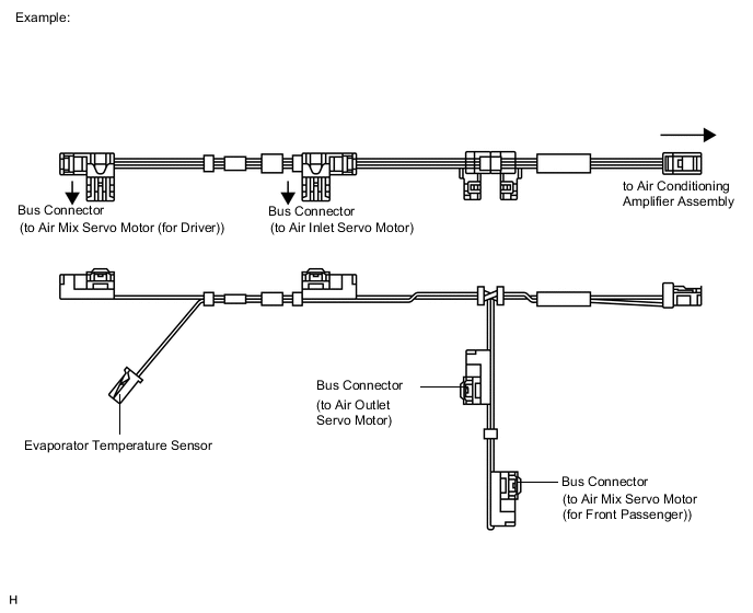
Bus connectors are used in the wire harness that connects the servo motors to the air conditioning amplifier assembly.
-
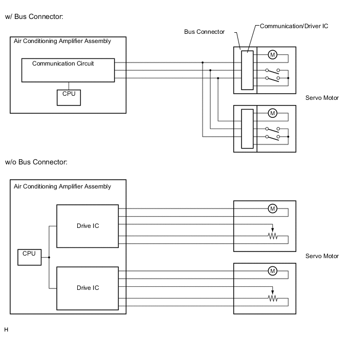
Each bus connector has a built-in communication/driver IC which communicates with the air conditioning amplifier assembly, actuates the servo motor, and has a position detection function. This enables bus communication for the servo motor wire harness, for a more lightweight construction and a reduced number of wires.
-
-
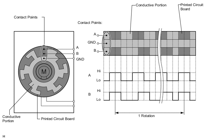
SERVO MOTOR
The pulse pattern type servo motor consists of a printed circuit board and a servo motor. The printed circuit board has three contact points, and can transmit two ON-OFF signals to the air conditioning amplifier assembly based on the difference of the pulse phases. The bus connector can detect the damper position and movement direction with these signals.
-
PTC HEATER ASSEMBLY (QUICK HEATER ASSEMBLY)
-
General
-
The PTC heater assembly (quick heater assembly) is located above the heater core in the air conditioning unit.
-
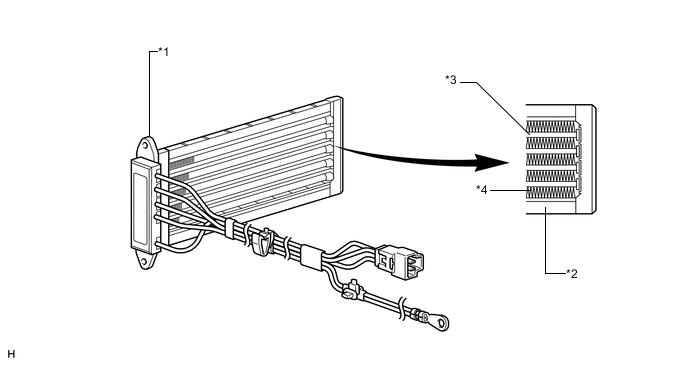
The PTC heater assembly (quick heater assembly) consists of a PTC element, aluminum fins, and brass plates. When current is applied to the PTC element, it generates heat to warm the air that passes through the unit.
Table 3. Text in Illustration *1 PTC Heater Assembly (Quick Heater Assembly) *2 Brass Plate *3 PTC Element *4 Aluminum Fin
-
-
PTC Heater Assembly (Quick Heater Assembly) Operating Conditions
-
The PTC heater assembly (quick heater assembly) is turned on and off by the air conditioning amplifier assembly in accordance with the engine coolant temperature, ambient temperature, temperature setting, and electrical load (generator power ratio).
-
-
-
AIR CONDITIONING THERMISTOR ASSEMBLY
-
An air conditioning thermistor assembly, in which the glass temperature sensor, glass surroundings temperature sensor and humidity sensor are integrated, is used.
-
The glass temperature sensor detects the surface temperature of the windshield using the built-in thermistor attached to the back of the sensor board, and outputs the signal to the air conditioning amplifier assembly.
-
The glass surroundings temperature sensor detects the air temperature near the windshield using the built-in thermistor, and outputs the signal to the air conditioning amplifier assembly.
-
The humidity sensor converts a change in the electrostatic capacity between the electrodes by allowing the humidity-sensing film to adsorb and desorb moisture in the cabin, and outputs the signal to the air conditioning amplifier assembly.
-
-
ECO MODE CONTROL
Under the control of ECO mode, the air conditioning amplifier assembly restricts the air conditioning system performance under specified conditions, thus improving fuel economy.
-
ROOM TEMPERATURE SENSOR (COOLER (ROOM TEMP. SENSOR) THERMISTOR)
The room temperature sensor (cooler (room temp. sensor) thermistor) detects the cabin temperature based on changes in the resistance of its built-in thermistor and sends a signal to the air conditioning amplifier assembly.
-
AMBIENT TEMPERATURE SENSOR (THERMISTOR ASSEMBLY)
The ambient temperature sensor (thermistor assembly) detects the outside temperature based on changes in the resistance of its built-in thermistor and sends a signal to the air conditioning amplifier assembly.
-
SOLAR SENSOR (AUTOMATIC LIGHT CONTROL SENSOR)
-
The solar sensor (automatic light control sensor) consists of a photo diode, two amplifier circuits for the solar sensor (automatic light control sensor), and a frequency converter circuit for the light control sensor.
-
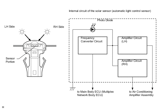
The solar sensor (automatic light control sensor) detects (in the form of changes in the current that flows through the built-in photo diode) the changes in the amount of sunlight from the LH and RH sides (2 directions) and outputs these sunlight strength signals to the air conditioning amplifier assembly.
-
-
AIR CONDITIONING PRESSURE SENSOR
The air conditioning pressure sensor detects the refrigerant pressure and outputs it to the air conditioning amplifier assembly in the form of voltage changes.