Click here
-
CHECK MAIN BODY ECU (MULTIPLEX NETWORK BODY ECU) AND INSTRUMENT PANEL JUNCTION BLOCK ASSEMBLY
-
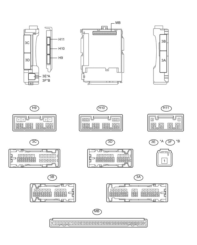
Disconnect the main body ECU (multiplex network body ECU) connectors.
Table 1. Text in Illustration *A for LHD *B for RHD -
Measure the resistance and voltage according to the value(s) in the table below.
Tip:Measure the values on the wire harness side with the connector disconnected.
Tester Connection Wiring Color Terminal Description Condition Specified Condition MB-30 (BECU) - Body ground - Auxiliary battery power supply Power switch off 11 to 14 V MB-31 (ALTB) - Body ground - Auxiliary battery power supply Power switch off 11 to 14 V MB-32 (IG) - Body ground - Ignition power supply (IG signal) Power switch on (IG)→ off 11 to 14 V → Below 1 V MB-29 (ACC) - Body ground - Ignition power supply (ACC signal) Power switch on (ACC)→ off 11 to 14 V → Below 1 V MB-11 (GND1) - Body ground - Ground Always Below 1 Ω H9-3 (GND2) - Body ground W-B - Body ground Ground Always Below 1 Ω H11-3 (LCTY) - Body ground* G - Body ground Rear door courtesy light switch LH input Rear door LH closed (OFF) 10 kΩ or higher H11-3 (LCTY) - Body ground* G - Body ground Rear door courtesy light switch LH input Rear door LH open (ON) Below 1 Ω H10-6 (RCTY) - Body ground* B - Body ground Rear door courtesy light switch RH input Rear door RH closed (OFF) 10 kΩ or higher H10-6 (RCTY) - Body ground* B - Body ground Rear door courtesy light switch RH input Rear door RH open (ON) Below 1 Ω
-
*: w/ Rear Seat Belt Warning
If the result is not as specified, there may be a malfunction in the wire harness.
-
-
-
CHECK COMBINATION METER ASSEMBLY
-

Disconnect the H14 combination meter assembly connector.
-
Measure the resistance according to the value(s) in the table below.
Tip:Measure the values on the wire harness side with the connector disconnected.
Tester Connection Wiring Color Terminal Description Condition Specified Condition H14-30 (ES) - Body ground BR - Body ground Ground Always Below 1 Ω H14-10 (PBKL) - Body ground*1 V - Body ground*3
Y - Body ground*4
Front passenger seat belt buckle switch signal Front passenger seat occupied, seat belt fastened 10 kΩ or higher H14-10 (PBKL) - Body ground*1 V - Body ground*3
Y - Body ground*4
Front passenger seat belt buckle switch signal Front passenger seat occupied, seat belt unfastened Below 1 Ω H14-9 (RLSB) - Body ground*2 Y - Body ground Rear LH seat belt buckle switch signal Rear LH seat belt fastened 10 kΩ or higher H14-9 (RLSB) - Body ground*2 Y - Body ground Rear LH seat belt buckle switch signal Rear LH seat belt unfastened Below 1 Ω H14-8 (RCSB) - Body ground*2 L - Body ground Rear center seat belt buckle switch signal Rear center seat belt fastened 10 kΩ or higher H14-8 (RCSB) - Body ground*2 L - Body ground Rear center seat belt buckle switch signal Rear center seat belt unfastened Below 1 Ω H14-7 (RRSB) - Body ground*2 LG- Body ground Rear RH seat belt buckle switch signal Rear RH seat belt fastened 10 kΩ or higher H14-7 (RRSB) - Body ground*2 LG - Body ground Rear RH seat belt buckle switch signal Rear RH seat belt unfastened Below 1 Ω
-
*1: w/o Occupant Classification System
-
*2: w/ Rear Seat Belt Warning
-
*3: for LHD
-
*4: for RHD
If the result is not as specified, there may be a malfunction in the wire harness.
-
-
Reconnect the H14 combination meter assembly connector.
-
Measure the voltage according to the value(s) in the table below.
Tester Connection Wiring Color Terminal Description Condition Specified Condition H14-22 (B) - Body ground W - Body ground Auxiliary battery power supply Power switch off 11 to 14 V H14-21 (IG+) - Body ground GR - Body ground Ignition power supply
(IG signal)
Power switch off Below 1 V H14-21 (IG+) - Body ground GR - Body ground Ignition power supply
(IG signal)
Power switch on (IG) 11 to 14 V If the result is not as specified, the combination meter assembly may have a malfunction.
-
-
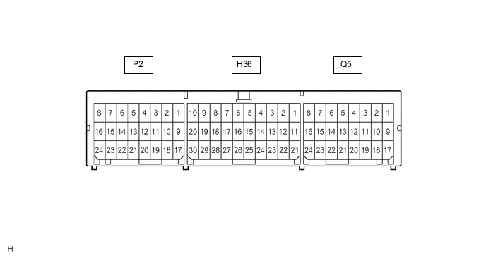
CHECK AIRBAG SENSOR ASSEMBLY
Terminal No. Terminal Symbol Destination P2-10*1 LBE+ Front seat inner belt assembly (driver seat) P2-18*1 LBE- Front seat inner belt assembly (driver seat) Q5-15*2 RBE+ Front seat inner belt assembly (driver seat) Q5-23*2 RBE- Front seat inner belt assembly (driver seat)
-
*1: for LHD
-
*2: for RHD
-