Click here
-
CHECK FRONT POWER SEAT SWITCH (FOR DRIVER)
-
for LHD:
-

Disconnect the X9 and X10 front power seat switch (for driver) connectors.
-
Measure the voltage and resistance according to the value(s) in the table below.
Tip:Measure the values on the wire harness side with the connector disconnected.
Terminal Connection Wiring Color Terminal Description Condition Specified Condition X9-2 (GND1) - Body ground W-B - Body ground Ground Always Below 1 Ω X9-7 (+B1) - X9-2 (GND1) R - W-B Power source Power switch off 11 to 14 V X10-12 (SYSB) - X9-2 (GND1) P - W-B System power source Power switch off 11 to 14 V X10-10 (DBCL) - Body ground GR - Body ground Driver seat belt buckle switch signal Driver seat belt fastened Below 1 Ω X10-10 (DBCL) - Body ground GR - Body ground Driver seat belt buckle switch signal Driver seat belt unfastened 10 kΩ or higher If the result is not as specified, there may be a malfunction on the wire harness side.
-
Reconnect the X9 and X10 front power seat switch (for driver) connectors.
-
Measure the voltage and resistance according to the value(s) in the table below.
Terminal Connection Wiring Color Terminal Description Condition Specified Condition X9-7 (+B1) - X9-2 (GND1) R - W-B Lumbar support adjuster power source Power switch off 11 to 14 V X9-2 (GND1) - Body ground W-B - Body ground Lumbar support adjuster ground Always Below 1 Ω X9-3 (SLD+) - X9-2 (GND1) L - W-B Slide motor signal (forward) Slide switch off Below 1 V Slide switch on (Forward) 11 to 14 V X9-4 (SLD-) - X9-2 (GND1) GR - W-B Slide motor signal (rearward) Slide switch off Below 1 V Slide switch on (Rearward) 11 to 14 V X9-5 (FRV-) - X9-2 (GND1) R - W-B Front vertical motor signal (downward) Front vertical switch off Below 1 V Front vertical switch on (Downward) 11 to 14 V X9-8 (FRV+) - X9-2 (GND1) B - W-B Front vertical motor signal (upward) Front vertical switch off Below 1 V Front vertical switch on (Upward) 11 to 14 V X9-9 (RCL+) - X9-2 (GND1) P - W-B Reclining motor signal (forward) Reclining switch off Below 1 V Reclining switch on (Forward) 11 to 14 V X9-11 (RCL-) - X9-2 (GND1) LG - W-B Reclining motor signal (rearward) Reclining switch off Below 1 V Reclining switch on (Rearward) 11 to 14 V X9-10 (LFT+) - X9-2 (GND1) V - W-B Lifter motor signal (upward) Lifter switch off Below 1 V Lifter switch on (Upward) 11 to 14 V X9-12 (LFT-) - X9-2 (GND1) G - W-B Lifter motor signal (downward) Lifter switch off Below 1 V Lifter switch on (Downward) 11 to 14 V X10-1 (SGND) - X9-2 (GND1) BR - W-B Position sensor round Always Below 1 Ω X10-5 (SSRS) - X10-1 (SGND) G- BR Slide position signal Slide function operating 4.5 to 4.8 V If the result is not as specified, the front power seat switch (for driver) may have a malfunction.
-
-
for RHD:
-

Disconnect the W9 and W10 front power seat switch (for driver) connectors.
-
Measure the voltage and resistance according to the value(s) in the table below.
Tip:Measure the values on the wire harness side with the connector disconnected.
Terminal Connection Wiring Color Terminal Description Condition Specified Condition W9-2 (GND1) - Body ground W-B - Body ground Ground Always Below 1 Ω W9-7 (+B1) - W9-2 (GND1) R - W-B Power source Power switch off 11 to 14 V W10-12 (SYSB) - W9-2 (GND1) P - W-B System power source Power switch off 11 to 14 V W10-10 (DBCL) - Body ground GR - Body ground Driver seat belt buckle switch signal Driver seat belt fastened Below 1 Ω W10-10 (DBCL) - Body ground GR - Body ground Driver seat belt buckle switch signal Driver seat belt unfastened 10 kΩ or higher If the result is not as specified, there may be a malfunction on the wire harness side.
-
Reconnect the W9 and W10 front power seat switch (for driver) connectors.
-
Measure the voltage and resistance according to the value(s) in the table below.
Terminal Connection Wiring Color Terminal Description Condition Specified Condition W9-7 (+B1) - W9-2 (GND1) R - W-B Lumbar support adjuster power source Power switch off 11 to 14 V W9-2 (GND1) - Body ground W-B - Body ground Lumbar support adjuster ground Always Below 1 Ω W9-3 (SLD+) - W9-2 (GND1) L - W-B Slide motor signal (forward) Slide switch off Below 1 V Slide switch on (Forward) 11 to 14 V W9-4 (SLD-) - W9-2 (GND1) GR - W-B Slide motor signal (rearward) Slide switch off Below 1 V Slide switch on (Rearward) 11 to 14 V W9-5 (FRV-) - W9-2 (GND1) R - W-B Front vertical motor signal (downward) Front vertical switch off Below 1 V Front vertical switch on (Downward) 11 to 14 V W9-8 (FRV+) - W9-2 (GND1) B - W-B Front vertical motor signal (upward) Front vertical switch off Below 1 V Front vertical switch on (Upward) 11 to 14 V W9-9 (RCL+) - W9-2 (GND1) P - W-B Reclining motor signal (forward) Reclining switch off Below 1 V Reclining switch on (Forward) 11 to 14 V W9-11 (RCL-) - W9-2 (GND1) LG - W-B Reclining motor signal (rearward) Reclining switch off Below 1 V Reclining switch on (Rearward) 11 to 14 V W9-10 (LFT+) - W9-2 (GND1) V - W-B Lifter motor signal (upward) Lifter switch off Below 1 V Lifter switch on (Upward) 11 to 14 V W9-12 (LFT-) - W9-2 (GND1) G - W-B Lifter motor signal (downward) Lifter switch off Below 1 V Lifter switch on (Downward) 11 to 14 V W10-1 (SGND) - W9-2 (GND1) BR - W-B Position sensor round Always Below 1 Ω W10-3 (SSFV) - W10-1 (SGND) R - BR Front vertical position signal Front vertical function operating 4.5 to 4.8 V W10-4 (SSRL) - W10-1 (SGND) P - BR Lifter position signal Lifter function operating 4.5 to 4.8 V W10-5 (SSRS) - W10-1 (SGND) G- BR Slide position signal Slide function operating 4.5 to 4.8 V W10-11 (SSRR) - W10-1 (SGND) V - BR Reclining position signal Reclining function operating 4.5 to 4.8 V If the result is not as specified, the front power seat switch (for driver) may have a malfunction.
-
-
-
CHECK FRONT POWER SEAT SWITCH (FOR FRONT PASSENGER)
-
for LHD:
-
Disconnect the W9 and W10 front power seat switch (for front passenger) connectors.
-
Measure the voltage and resistance according to the value(s) in the table below.
Tip:Measure the values on the wire harness side with the connector disconnected.
Terminal Connection Wiring Color Terminal Description Condition Specified Condition W9-2 (GND) - Body ground W-B - Body ground Ground Always Below 1 Ω W9-7 (+B) - W9-2 (GND) R - W-B Power source Power switch off 11 to 14 V W10-12 (SYSB) - W9-2 (GND) P - W-B System power source Power switch off 11 to 14 V If the result is not as specified, there may be a malfunction on the wire harness side.
-
Reconnect the W9 and W10 front power seat switch (for front passenger) connectors.
-
Measure the voltage and resistance according to the value(s) in the table below.
Terminal Connection Wiring Color Terminal Description Condition Specified Condition W9-7 (+B) - W9-2 (GND) R - W-B Lumbar support adjuster power source Power switch off 11 to 14 V W9-2 (GND) - Body ground W-B - Body ground Lumbar support adjuster ground Always Below 1 Ω W10-2 (SLDF) - W9-2 (GND)* L - W-B Power seat switch assembly signal Slide switch off Below 1 V Slide switch on (Forward) 11 to 14 V W10-6 (SLDR) - W9-2 (GND)* GR - W-B Power seat switch assembly signal Slide switch off Below 1 V Slide switch on (Rearward) 11 to 14 V W10-9 (RCLF) - W9-2 (GND)* P - W-B Power seat switch assembly signal Reclining switch off Below 1 V Reclining switch on (Forward) 11 to 14 V W10-10 (RCLR) - W9-2 (GND)* LG - W-B Power seat switch assembly signal Reclining switch off Below 1 V Reclining switch on (Rearward) 11 to 14 V W9-3 (SLD+) - W9-2 (GND) L - W-B Slide motor signal (forward) Slide switch off Below 1 V Slide switch on (Forward) 11 to 14 V W9-4 (SLD-) - W9-2 (GND) GR - W-B Slide motor signal (rearward) Slide switch off Below 1 V Slide switch on (Rearward) 11 to 14 V W9-5 (FRV-) - W9-2 (GND) R - W-B Front vertical motor signal (downward) Front vertical switch off Below 1 V Front vertical switch on (Downward) 11 to 14 V W9-8 (FRV+) - W9-2 (GND) B - W-B Front vertical motor signal (upward) Front vertical switch off Below 1 V Front vertical switch on (Upward) 11 to 14 V W9-9 (RCL+) - W9-2 (GND) P - W-B Reclining motor signal (forward) Reclining switch off Below 1 V Reclining switch on (Forward) 11 to 14 V W9-11 (RCL-) - W9-2 (GND) LG - W-B Reclining motor signal (rearward) Reclining switch off Below 1 V Reclining switch on (Rearward) 11 to 14 V W9-10 (LFT+) - W9-2 (GND) V - W-B Lifter motor signal (upward) Lifter switch off Below 1 V Lifter switch on (Upward) 11 to 14 V W9-12 (LFT-) - W9-2 (GND) G - W-B Lifter motor signal (downward) Lifter switch off Below 1 V Lifter switch on (Downward) 11 to 14 V W10-1 (SGND) - W9-2 (GND) BR - W-B Position sensor round Always Below 1 Ω W10-3 (SSFV) - W10-1 (SGND) R - BR Front vertical position signal Front vertical function operating 4.5 to 4.8 V W10-4 (SSRL) - W10-1 (SGND) P - BR Lifter position signal Lifter function operating 4.5 to 4.8 V W10-5 (SSRS) - W10-1 (SGND) G- BR Slide position signal Slide function operating 4.5 to 4.8 V W10-11 (SSRR) - W10-1 (SGND) V - BR Reclining position signal Reclining function operating 4.5 to 4.8 V
-
*: w/ Power Seat Switch Assembly
If the result is not as specified, the front power seat switch (for front passenger) may have a malfunction.
-
-
-
for RHD:
-
Disconnect the X9 and X10 front power seat switch (for front passenger) connectors.
-
Measure the voltage and resistance according to the value(s) in the table below.
Tip:Measure the values on the wire harness side with the connector disconnected.
Terminal Connection Wiring Color Terminal Description Condition Specified Condition X9-2 (GND) - Body ground W-B - Body ground Ground Always Below 1 Ω X9-7 (+B) - X9-2 (GND) R - W-B Power source Always 11 to 14 V X10-12 (SYSB) - X9-2 (GND) P - W-B System power source Always 11 to 14 V If the result is not as specified, there may be a malfunction on the wire harness side.
-
Reconnect the X9 and X10 front power seat switch (for front passenger) connectors.
-
Measure the voltage and resistance according to the value(s) in the table below.
Terminal Connection Wiring Color Terminal Description Condition Specified Condition X9-7 (+B) - X9-2 (GND) R - W-B Lumbar support adjuster power source Always 11 to 14 V X9-2 (GND) - Body ground W-B - Body ground Lumbar support adjuster ground Always Below 1 Ω X9-3 (SLD+) - X9-2 (GND) L - W-B Slide motor signal (forward) Slide switch off Below 1 V Slide switch on (Forward) 11 to 14 V X9-4 (SLD-) - X9-2 (GND) GR - W-B Slide motor signal (rearward) Slide switch off Below 1 V Slide switch on (Rearward) 11 to 14 V X9-5 (FRV-) - X9-2 (GND) R - W-B Front vertical motor signal (downward) Front vertical switch off Below 1 V Front vertical switch on (Downward) 11 to 14 V X9-8 (FRV+) - X9-2 (GND) B - W-B Front vertical motor signal (upward) Front vertical switch off Below 1 V Front vertical switch on (Upward) 11 to 14 V X9-9 (RCL+) - X9-2 (GND) P - W-B Reclining motor signal (forward) Reclining switch off Below 1 V Reclining switch on (Forward) 11 to 14 V X9-11 (RCL-) - X9-2 (GND) LG - W-B Reclining motor signal (rearward) Reclining switch off Below 1 V Reclining switch on (Rearward) 11 to 14 V X9-10 (LFT+) - X9-2 (GND) V - W-B Lifter motor signal (upward) Lifter switch off Below 1 V Lifter switch on (Upward) 11 to 14 V X9-12 (LFT-) - X9-2 (GND) G - W-B Lifter motor signal (downward) Lifter switch off Below 1 V Lifter switch on (Downward) 11 to 14 V X10-1 (SGND) - X9-2 (GND) BR - W-B Position sensor round Always Below 1 Ω If the result is not as specified, the front power seat switch (for front passenger) may have a malfunction.
-
-
-

CHECK OUTER MIRROR CONTROL ECU ASSEMBLY
Table 1. Text in Illustration *A
-
for Driver (for LHD)
-
for Front Passenger (for RHD)
*B
-
for Front Passenger (for LHD)
-
for Driver (for RHD)
-
for Driver (for LHD) or Front Passenger (for RHD):
-
Disconnect the M9 outer mirror control ECU assembly connector.
-
Measure the voltage and resistance according to the value(s) in the table below.
Tip:Measure the values on the wire harness side with the connector disconnected.
Tester Connection Wiring Color Terminal Description Condition Specified Condition M9-7 (GND) - Body ground W-B - Body ground Ground Always Below 1 Ω M9-14 (BDR) - M9-7 (GND) GR - W-B Power source Power switch off 11 to 14 V M9-5 (SIG) - M9-7 (GND) BE - W-B Power source (IG) Power switch off Below 1 V Power switch on (IG) 11 to 14 V M9-6 (CPUB) - M9-7 (GND) W - W-B Power source Power switch off 11 to 14 V If the result is not as specified, there may be a malfunction in the wire harness.
-
Reconnect the M9 outer mirror control ECU assembly connector.
-
Measure the voltage according to the value(s) in the table below.
Tester Connection Wiring Color Terminal Description Condition Specified Condition M9-2 (M1) - M9-7 (GND) L - W-B M1 switch signal for seat memory switch M1 switch on Below 1 V M1 switch off 11 to 14 V M9-3 (M2) - M9-7 (GND) Y - W-B M2 switch signal for seat memory switch M2 switch on Below 1 V M2 switch off 11 to 14 V M9-4 (M3) - M9-7 (GND) GR - W-B M3 switch signal for seat memory switch M3 switch on Below 1 V M3 switch off 11 to 14 V M9-1 (MM) - M9-7 (GND) P - W-B SET switch signal for seat memory switch SET switch on Below 1 V SET switch off 11 to 14 V If the result is not as specified, the outer mirror control ECU assembly may have a malfunction.
-
-
for Front Passenger (for LHD) or for Driver (for RHD):
-
Disconnect the L10 outer mirror control ECU assembly connector.
-
Measure the voltage and resistance according to the value(s) in the table below.
Tip:Measure the values on the wire harness side with the connector disconnected.
Tester Connection Wiring Color Terminal Description Condition Specified Condition L10-7 (GND) - Body ground W-B - Body ground Ground Always Below 1 Ω L10-14 (BDR) - L10-7 (GND) GR - W-B Power source Power switch off 11 to 14 V L10-5 (SIG) - L10-7 (GND) BE - W-B Power source (IG) Power switch off Below 1 V Power switch on (IG) 11 to 14 V L10-6 (CPUB) - L10-7 (GND) W - W-B Power source Power switch off 11 to 14 V If the result is not as specified, there may be a malfunction in the wire harness.
-
Reconnect the L10 outer mirror control ECU assembly connector.
-
Measure the voltage according to the value(s) in the table below.
Tester Connection Wiring Color Terminal Description Condition Specified Condition L10-2 (M1) - L10-7 (GND) L - W-B M1 switch signal for seat memory switch M1 switch on Below 1 V M1 switch off 11 to 14 V L10-3 (M2) - L10-7 (GND) Y - W-B M2 switch signal for seat memory switch M2 switch on Below 1 V M2 switch off 11 to 14 V L10-4 (M3) - L10-7 (GND) GR - W-B M3 switch signal for seat memory switch M3 switch on Below 1 V M3 switch off 11 to 14 V L10-1 (MM) - L10-7 (GND) P - W-B SET switch signal for seat memory switch SET switch on Below 1 V SET switch off 11 to 14 V If the result is not as specified, the outer mirror control ECU assembly may have a malfunction.
-
-
-
CHECK MAIN BODY ECU (MULTIPLEX NETWORK BODY ECU) AND INSTRUMENT PANEL JUNCTION BLOCK ASSEMBLY
-
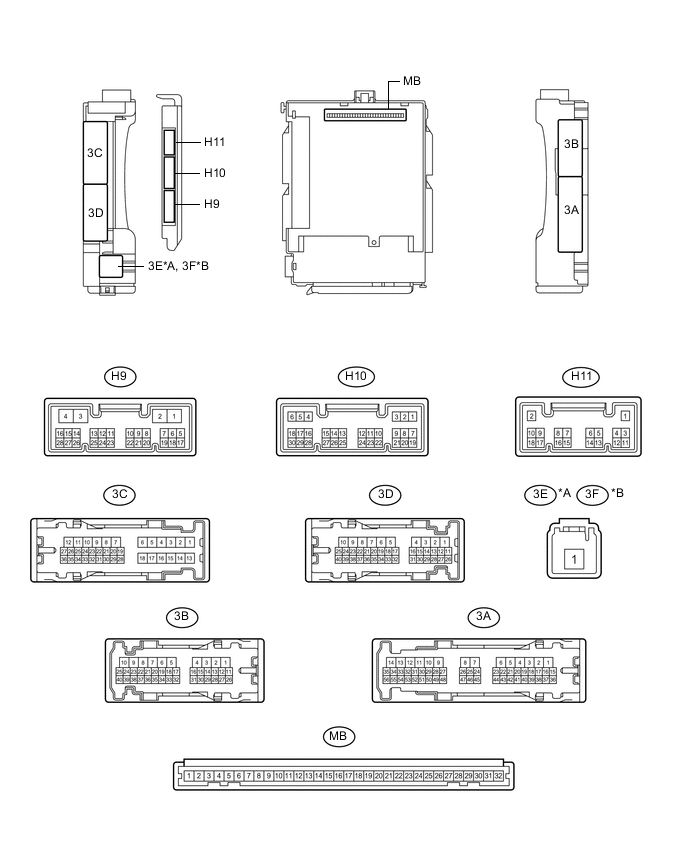
Disconnect the MB and H9 main body ECU (multiplex network body ECU) connectors.
Table 2. Text in Illustration *A for LHD *B for RHD -
Measure the voltage and resistance according to the value(s) in the table below.
Tip:Measure the values on the wire harness side with the connector disconnected.
Tester Connection Wiring Color Terminal Description Condition Specified Condition MB-30 (BECU) - Body ground - Auxiliary battery power supply Power switch off 11 to 14 V MB-31 (ALTB) - Body ground - Auxiliary battery power supply Power switch off 11 to 14 V MB-32 (IG) - Body ground - Ignition power supply (IG signal) Power switch on (IG) → off 11 to 14 V → Below 1 V MB-29 (ACC) - Body ground - Ignition power supply (ACC signal) Power switch on (ACC) → off 11 to 14 V → Below 1 V MB-11 (GND1) - Body ground - Ground Always Below 1 Ω H9-3 (GND2) - Body ground W-B - Body ground Ground Always Below 1 Ω MB-2 (FLCY) - Body ground*1 - Front door courtesy light switch LH input Front door LH closed (OFF) → open (ON) 10 kΩ or higher → Below 1 Ω MB-4 (FRCY) - Body ground*2 - Front door courtesy light switch RH input Front door RH closed (OFF) → open (ON) 10 kΩ or higher → Below 1 Ω
-
*1: for LHD
-
*2: for RHD
If the result is not as specified, there may be a malfunction in the wire harness.
-
-