| DTC Code | DTC Name |
|---|---|
| B2658 | Short in Sensor with Motor Power Supply Circuit |
DESCRIPTION
This DTC is stored when a power seat motor operates (a position control sensor is being supplied with power) and the power supply voltage does not rise to the specified value.
| DTC Code | DTC Detection Condition | Trouble Area |
|---|---|---|
| B2658 | Problem with the voltage supplied to the position control sensor. |
|
PROCEDURE
- Click here
CHECK FOR DTC
-
Clear the DTCs (Click here).
-
Check for DTCs (Click here).
Result Result Proceed to DTC is not output A DTC output from "Driver Seat" B DTC output from "Passenger Seat" C
- A
USE SIMULATION METHOD TO CHECK (Click here)
- BClick here
- CClick here
-
- Click here
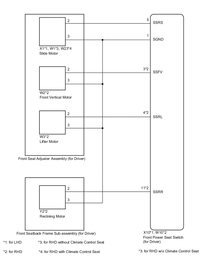
CHECK HARNESS AND CONNECTOR (FRONT POWER SEAT SWITCH (FOR DRIVER) - SLIDE MOTOR)
-
Disconnect the X10*1 or W10*2 front power seat switch (for driver) connector.
-
Disconnect the X1*1 or W1*3, W23*4 slide motor connector.
-
*1: for LHD
-
*2: for RHD
-
*3: for RHD without Climate Control Seat System
-
*4: for RHD with Climate Control Seat System
-
-
Measure the resistance according to the value(s) in the table below.
Standard Resistance Table 1. for LHD Tester Connection Condition Specified Condition X10-5 (SSRS) - X1-2 Always Below 1 Ω X10-1 (SGND) - X1-3 Always Below 1 Ω X10-5 (SSRS) - X10-1 (SGND) Always 10 kΩ or higher X10-5 (SSRS) - Body ground Always 10 kΩ or higher X10-1 (SGND) - Body ground Always 10 kΩ or higher Table 2. for RHD Tester Connection Condition Specified Condition W10-5 (SSRS) - W1-2*1 Always Below 1 Ω W10-1 (SGND) - W1-3*1 Always Below 1 Ω W10-5 (SSRS) - W23-2*2 Always Below 1 Ω W10-1 (SGND) - W23-3*2 Always Below 1 Ω W10-5 (SSRS) - W10-1 (SGND) Always 10 kΩ or higher W10-5 (SSRS) - Body ground Always 10 kΩ or higher W10-1 (SGND) - Body ground Always 10 kΩ or higher
-
*1: for RHD without Climate Control Seat System
-
*2: for RHD with Climate Control Seat System
-
- OKClick here
- NG
REPAIR OR REPLACE HARNESS OR CONNECTOR
-
- Click here
CHECK FRONT POWER SEAT SWITCH (FOR DRIVER) (SLIDE MOTOR CIRCUIT)
-
Measure the voltage according to the value(s) in the table below.
Standard Voltage Table 3. for LHD Tester Connection Condition Specified Condition X1-2 - X1-3 Sliding switch on 4.8 to 5.1 V Table 4. for RHD Tester Connection Condition Specified Condition W1-2 - W1-3*1 Sliding switch on 4.8 to 5.1 V W23-2 - W23-3*2 Sliding switch on 4.8 to 5.1 V
-
*1: for RHD without Climate Control Seat System
-
*2: for RHD with Climate Control Seat System
-
- OKClick here
- NG
REPLACE FRONT POWER SEAT SWITCH (FOR DRIVER) (Click here)
-
- Click here
CHECK HARNESS AND CONNECTOR (FRONT POWER SEAT SWITCH (FOR DRIVER) - FRONT VERTICAL MOTOR)
-
Disconnect the W2 front vertical motor connector.
-
Measure the resistance according to the value(s) in the table below.
Standard Resistance Tester Connection Condition Specified Condition W10-3 (SSFV) - W2-2 Always Below 1 Ω W10-1 (SGND) - W2-3 Always Below 1 Ω W10-3 (SSFV) - W10-1 (SGND) Always 10 kΩ or higher W10-3 (SSFV) - Body ground Always 10 kΩ or higher W10-1 (SGND) - Body ground Always 10 kΩ or higher
- OKClick here
- NG
REPAIR OR REPLACE HARNESS OR CONNECTOR
-
- Click here
CHECK FRONT POWER SEAT SWITCH (FOR DRIVER) (FRONT VERTICAL MOTOR CIRCUIT)
-
Measure the voltage according to the value(s) in the table below.
Standard Voltage Tester Connection Condition Specified Condition W2-2 - W2-3 Front vertical switch on 4.8 to 5.1 V
- OKClick here
- NG
REPLACE FRONT POWER SEAT SWITCH (FOR DRIVER) (Click here)
-
- Click here
CHECK HARNESS AND CONNECTOR (FRONT POWER SEAT SWITCH (FOR DRIVER) - LIFTER MOTOR)
-
Disconnect the W3 lifter motor connector.
-
Measure the resistance according to the value(s) in the table below.
Standard Resistance Tester Connection Condition Specified Condition W10-4 (SSRL) - W3-2 Always Below 1 Ω W10-1 (SGND) - W3-3 Always Below 1 Ω W10-4 (SSRL) - W10-1 (SGND) Always 10 kΩ or higher W10-4 (SSRL) - Body ground Always 10 kΩ or higher W10-1 (SGND) - Body ground Always 10 kΩ or higher
- OKClick here
- NG
REPAIR OR REPLACE HARNESS OR CONNECTOR
-
- Click here
CHECK FRONT POWER SEAT SWITCH (FOR DRIVER) (LIFTER MOTOR CIRCUIT)
-
Measure the voltage according to the value(s) in the table below.
Standard Voltage Tester Connection Condition Specified Condition W3-2 - W3-3 Lifter switch on 4.8 to 5.1 V
- OKClick here
- NG
REPLACE FRONT POWER SEAT SWITCH (FOR DRIVER) (Click here)
-
- Click here
REPLACE FRONT SEAT ADJUSTER ASSEMBLY (FOR DRIVER)
-
Replace the front seat adjuster assembly (for driver) (Click here).
-
Clear the DTCs (Click here).
-
Check for DTCs (Click here).
OK DTC B2658 is not output.
- OK
END (FRONT SEAT ADJUSTER ASSEMBLY (FOR DRIVER) WAS DEFECTIVE)
- NGClick here
-
- Click here
CHECK HARNESS AND CONNECTOR (FRONT POWER SEAT SWITCH (FOR DRIVER) - RECLINING MOTOR)
-
Disconnect the W10 front power seat switch (for driver) connector.
-
Disconnect the Y2 reclining motor connector.
-
Measure the resistance according to the value(s) in the table below.
Standard Resistance Tester Connection Condition Specified Condition W10-11 (SSRR) - Y2-2 Always Below 1 Ω W10-1 (SGND) - Y2-3 Always Below 1 Ω W10-11 (SSRR) - W10-1 (SGND) Always 10 kΩ or higher W10-11 (SSRR) - Body ground Always 10 kΩ or higher W10-1 (SGND) - Body ground Always 10 kΩ or higher
- OKClick here
- NG
REPAIR OR REPLACE HARNESS OR CONNECTOR
-
- Click here
CHECK FRONT POWER SEAT SWITCH (FOR DRIVER) (RECLINING MOTOR CIRCUIT)
-
Measure the voltage according to the value(s) in the table below.
Standard Voltage Tester Connection Condition Specified Condition Y2-2 - Y2-3 Reclining switch on 4.8 to 5.1 V
- OKClick here
- NG
REPLACE FRONT POWER SEAT SWITCH (FOR DRIVER) (Click here)
-
- Click here
REPLACE FRONT SEATBACK FRAME SUB-ASSEMBLY (FOR DRIVER)
-
Replace the front seatback frame sub-assembly (for driver) (Click here).
-
Clear the DTCs (Click here).
-
Check for DTCs (Click here).
OK DTC B2658 is not output.
- OK
END (FRONT SEATBACK FRAME SUB-ASSEMBLY (FOR DRIVER) WAS DEFECTIVE)
- NG
REPLACE FRONT POWER SEAT SWITCH (FOR DRIVER) (Click here)
-
- Click here
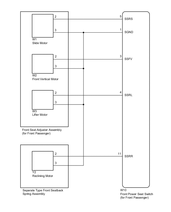
CHECK HARNESS AND CONNECTOR (FRONT POWER SEAT SWITCH (FOR FRONT PASSENGER) - SLIDE MOTOR)
-
Disconnect the W10 front power seat switch (for front passenger) connector.
-
Disconnect the W1 slide motor connector.
-
Measure the resistance according to the value(s) in the table below.
Standard Resistance Tester Connection Condition Specified Condition W10-5 (SSRS) - W1-2 Always Below 1 Ω W10-1 (SGND) - W1-3 Always Below 1 Ω W10-5 (SSRS) - W10-1 (SGND) Always 10 kΩ or higher W10-5 (SSRS) - Body ground Always 10 kΩ or higher W10-1 (SGND) - Body ground Always 10 kΩ or higher
- OKClick here
- NG
REPAIR OR REPLACE HARNESS OR CONNECTOR
-
- Click here
CHECK FRONT POWER SEAT SWITCH (FOR FRONT PASSENGER) (SLIDE MOTOR CIRCUIT)
-
Measure the voltage according to the value(s) in the table below.
Standard Voltage Tester Connection Condition Specified Condition W1-2 - W1-3 Sliding switch on 4.8 to 5.1 V
- OKClick here
- NG
REPLACE FRONT POWER SEAT SWITCH (FOR FRONT PASSENGER) (Click here)
-
- Click here
CHECK HARNESS AND CONNECTOR (FRONT POWER SEAT SWITCH (FOR FRONT PASSENGER) - FRONT VERTICAL MOTOR)
-
Disconnect the W2 front vertical motor connector.
-
Measure the resistance according to the value(s) in the table below.
Standard Resistance Tester Connection Condition Specified Condition W10-3 (SSFV) - W2-2 Always Below 1 Ω W10-1 (SGND) - W2-3 Always Below 1 Ω W10-3 (SSFV) - W10-1 (SGND) Always 10 kΩ or higher W10-3 (SSFV) - Body ground Always 10 kΩ or higher W10-1 (SGND) - Body ground Always 10 kΩ or higher
- OKClick here
- NG
REPAIR OR REPLACE HARNESS OR CONNECTOR
-
- Click here
CHECK FRONT POWER SEAT SWITCH (FOR FRONT PASSENGER) (FRONT VERTICAL MOTOR CIRCUIT)
-
Measure the voltage according to the value(s) in the table below.
Standard Voltage Tester Connection Condition Specified Condition W2-2 - W2-3 Front vertical switch on 4.8 to 5.1 V
- OKClick here
- NG
REPLACE FRONT POWER SEAT SWITCH (FOR FRONT PASSENGER) (Click here)
-
- Click here
CHECK HARNESS AND CONNECTOR (FRONT POWER SEAT SWITCH (FOR FRONT PASSENGER) - LIFTER MOTOR)
-
Disconnect the W3 lifter motor connector.
-
Measure the resistance according to the value(s) in the table below.
Standard Resistance Tester Connection Condition Specified Condition W10-4 (SSRL) - W3-2 Always Below 1 Ω W10-1 (SGND) - W3-3 Always Below 1 Ω W10-4 (SSRL) - W10-1 (SGND) Always 10 kΩ or higher W10-4 (SSRL) - Body ground Always 10 kΩ or higher W10-1 (SGND) - Body ground Always 10 kΩ or higher
- OKClick here
- NG
REPAIR OR REPLACE HARNESS OR CONNECTOR
-
- Click here
CHECK FRONT POWER SEAT SWITCH (FOR FRONT PASSENGER) (LIFTER MOTOR CIRCUIT)
-
Measure the voltage according to the value(s) in the table below.
Standard Voltage Tester Connection Condition Specified Condition W3-2 - W3-3 Lifter switch on 4.8 to 5.1 V
- OKClick here
- NG
REPLACE FRONT POWER SEAT SWITCH (FOR FRONT PASSENGER) (Click here)
-
- Click here
REPLACE FRONT SEAT ADJUSTER ASSEMBLY (FOR FRONT PASSENGER)
-
Replace the front seat adjuster assembly (for front passenger) (Click here).
-
Clear the DTCs (Click here).
-
Check for DTCs (Click here).
OK DTC B2658 is not output.
- OK
END (FRONT SEAT ADJUSTER ASSEMBLY (FOR FRONT PASSENGER) WAS DEFECTIVE)
- NGClick here
-
- Click here
CHECK HARNESS AND CONNECTOR (FRONT POWER SEAT SWITCH (FOR FRONT PASSENGER) - RECLINING MOTOR)
-
Disconnect the W10 front power seat switch (for front passenger) connector.
-
Disconnect the Y2 reclining motor connector.
-
Measure the resistance according to the value(s) in the table below.
Standard Resistance Tester Connection Condition Specified Condition W10-11 (SSRR) - Y2-2 Always Below 1 Ω W10-1 (SGND) - Y2-3 Always Below 1 Ω W10-11 (SSRR) - W10-1 (SGND) Always 10 kΩ or higher W10-11 (SSRR) - Body ground Always 10 kΩ or higher W10-1 (SGND) - Body ground Always 10 kΩ or higher
- OKClick here
- NG
REPAIR OR REPLACE HARNESS OR CONNECTOR
-
- Click here
CHECK FRONT POWER SEAT SWITCH (FOR FRONT PASSENGER) (RECLINING MOTOR CIRCUIT)
-
Measure the voltage according to the value(s) in the table below.
Standard Voltage Tester Connection Condition Specified Condition Y2-2 - Y2-3 Reclining switch on 4.8 to 5.1 V
- OKClick here
- NG
REPLACE FRONT POWER SEAT SWITCH (FOR FRONT PASSENGER) (Click here)
-
- Click here
REPLACE SEPARATE TYPE FRONT SEATBACK SPRING ASSEMBLY
-
Replace the separate type front seatback spring assembly (Click here).
-
Clear the DTCs (Click here).
-
Check for DTCs (Click here).
OK DTC B2658 is not output.
- OK
END (SEPARATE TYPE FRONT SEATBACK SPRING ASSEMBLY WAS DEFECTIVE)
- NG
REPLACE FRONT POWER SEAT SWITCH (FOR FRONT PASSENGER) (Click here)
-