PROCEDURE
- Click here
INSTALL DRAIN COOLER HOSE
-
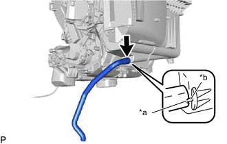
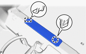
Align the hose notch and rib as shown in the illustration and install the drain cooler hose.
Table 1. Text in Illustration *a Hose Notch *b Rib
-
- Click here
INSTALL ASPIRATOR PIPE
-
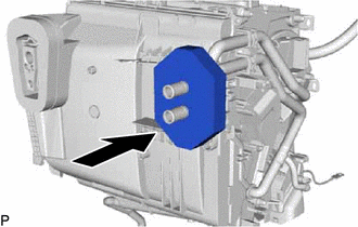
Engage the 2 claws to install the aspirator pipe.
-
- Click here
INSTALL COOLER THERMISTOR HOSE
-
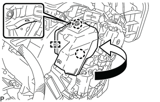
Install the cooler thermistor hose.
-
Engage the clamp.
-
- Click here
INSTALL HEATER PACKING
-
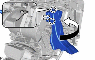
Install the heater packing as shown in the illustration.
-
- Click here
INSTALL NO. 4 AIR DUCT SUB-ASSEMBLY (for RHD)
-
Engage the guide and 2 claws to install the No. 4 air duct sub-assembly as shown in the illustration.
-
- Click here
INSTALL NO. 1 AIR DUCT SUB-ASSEMBLY
-
Engage the guide and 2 claws to install the No. 1 air duct sub-assembly as shown in the illustration.
-
- Click here
INSTALL NO. 6 HEATER TO REGISTER DUCT ASSEMBLY
-
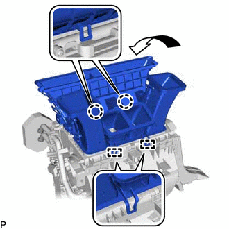
Engage the 2 guides and 2 claws to install the No. 6 heater to register duct assembly as shown in the illustration.
-
- Click here
INSTALL AIR CONDITIONING HARNESS ASSEMBLY
-
Engage each clamp to install the air conditioning harness assembly.
-
Connect each connector.
-
- Click here
INSTALL BLOWER ASSEMBLY
for LHD: (Click here)
for RHD: (Click here)
- Click here
INSTALL AIR CONDITIONING UNIT ASSEMBLY
-
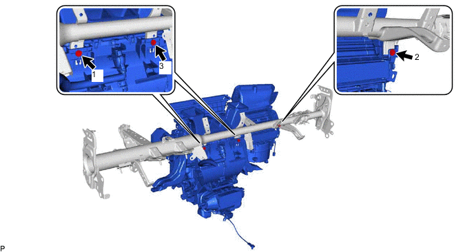
Install the air conditioning unit assembly to the instrument panel reinforcement assembly with the 3 bolts.
9.8 N*m 100 kgf*cm 87 in.*lbf Note:Tighten the bolts in the order shown in the illustration to install the air conditioning unit assembly.
-
- Click here
INSTALL INSTRUMENT PANEL REINFORCEMENT ASSEMBLY WITH AIR CONDITIONING UNIT
Note:
-
Be sure to support the air conditioning unit assembly when installing it because failure to do so may cause the bracket of the air conditioning unit assembly to break.
-
When installing the air conditioning unit, eliminate static electricity by touching the vehicle body to prevent the components from being damaged.
-
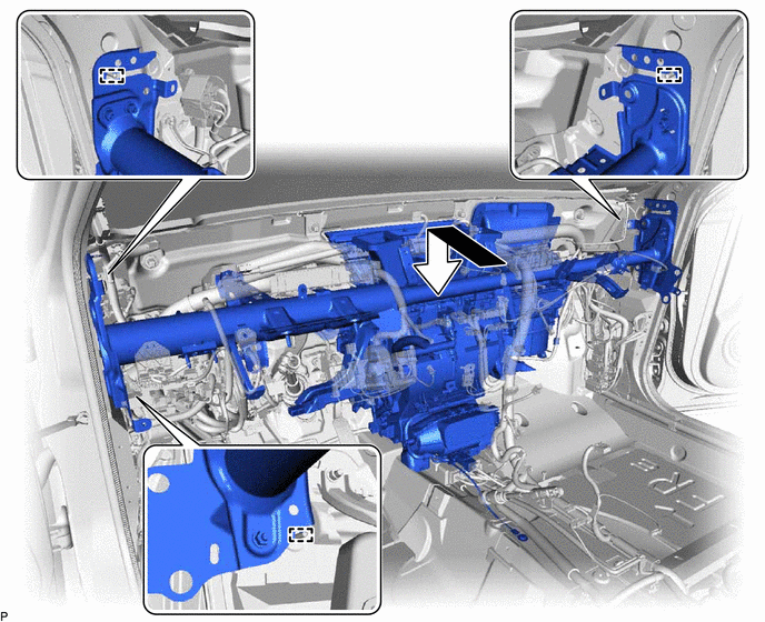
Engage the 3 guides and temporarily install the instrument panel reinforcement assembly with air conditioning unit as shown in the illustration.
-
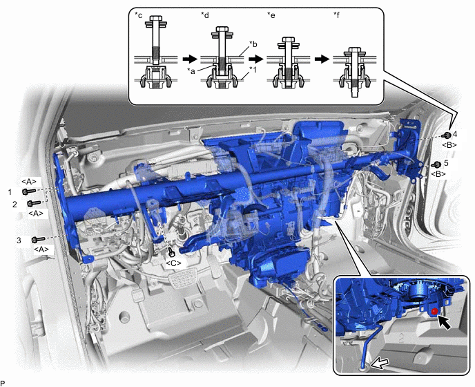
Install the instrument panel reinforcement assembly with the 3 bolts <A> and 2 new bolts <B> in the order shown in the illustration.
Table 2. Text in Illustration *1 Instrument Panel Reinforcement Assembly - - *a Movable Collar *b Body *c Step 1 *d Step 2 *e Step 3 *f Step 4 20 N*m 204 kgf*cm 15 ft.*lbf Note:Tighten the bolts in the order shown in the illustration to install the reinforcement assembly.
-
Install the bolt <C>.
15 N*m 153 kgf*cm 11 ft.*lbf -
Install the instrument panel reinforcement assembly with air conditioning unit with the nut.
9.8 N*m 100 kgf*cm 87 in.*lbf -
Pass the drain cooler hose through the vehicle securely.
Note:Connect the cooler drain hose firmly to prevent water leaks.
-
Install the 2 bolts.
9.8 N*m 100 kgf*cm 87 in.*lbf Note:Tighten the bolts in the order shown in the illustration.
-
Install the 2 hole plugs.
-
for LHD:
-
Engage each clamp.
-
Connect the connector.
-
Connect the 4 earth wires with the 4 bolts.
8.4 N*m 86 kgf*cm 74 in.*lbf -
Connect the protector with the nut.
8.0 N*m 82 kgf*cm 71 in.*lbf -
Connect the connector holder with the 2 nuts.
8.0 N*m 82 kgf*cm 71 in.*lbf
-
-
for RHD:
-
Engage each clamp.
-
Connect the connector.
-
Connect the 4 earth wires with the 4 bolts.
8.4 N*m 86 kgf*cm 74 in.*lbf -
Connect the connector holder with the 2 nuts.
8.0 N*m 82 kgf*cm 71 in.*lbf
-
-
Engage the claw to connect the airbag connector as shown in the illustration.
-
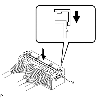
Engage the 2 claws to lock the retainer as shown in the illustration.
Table 3. Text in Illustration *a Retainer -
Connect the connector.
-
Install the bolt.
20 N*m 199 kgf*cm 14 ft.*lbf -
for LHD:
-
Install the shift lever support (Click here).
-
Install the lower shift lever assembly (Click here).
-
-
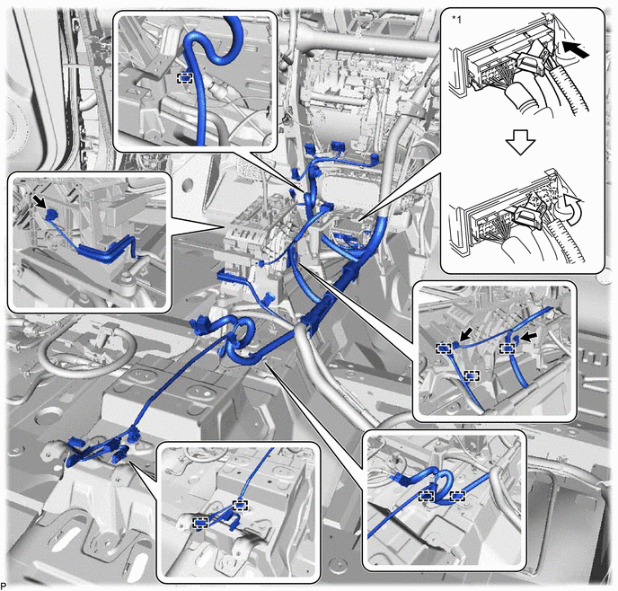
Engage each clamp.
Table 4. Text in Illustration *1 Airbag Sensor Assembly - - -
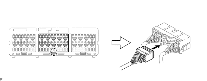
Connect each connector.
-
Connect the connector to the airbag sensor assembly as shown in the illustration.
Note:When connecting any airbag connector, take care not to damage the airbag wire harness.
-
Engage the 3 claws to close the 3 clamps as shown in the illustration.
-
w/ Telematics Transceiver:
-
Engage each clamp.
-
-
Engage each clamp.
-
- Click here
INSTALL INSTRUMENT PANEL SAFETY PAD CAP
-
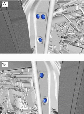
Install 5 new instrument panel safety pad caps.
Table 5. Text in Illustration *A for LH Side *B for RH Side
-
- Click here
INSTALL NO. 1 HEATER TO REGISTER DUCT
-
Install the No. 1 heater to register duct with the 3 clips.
-
Engage the clamp.
-
- Click here
INSTALL NO. 2 INSTRUMENT PANEL BRACE SUB-ASSEMBLY
-
Install the No. 2 instrument panel brace sub-assembly with the bolt and 2 nuts.
20 N*m 204 kgf*cm 15 ft.*lbf -
Install the screw.
-
Engage each clamp.
-
Connect the connector.
-
Connect the earth wire with the bolt.
8.4 N*m 86 kgf*cm 74 in.*lbf
-
- Click here
INSTALL NO. 1 INSTRUMENT PANEL BRACE SUB-ASSEMBLY
-
Install the No. 1 instrument panel brace sub-assembly with the bolt and 2 nuts.
20 N*m 204 kgf*cm 15 ft.*lbf -
Install the screw.
-
Engage the clamp.
-
Connect the connector.
-
- Click here
INSTALL COOLER (ROOM TEMP. SENSOR) THERMISTOR
-
Connect the cooler thermistor hose and connector to install the cooler (room temp. sensor) thermistor.
-
- Click here
INSTALL NO. 1 CONSOLE BOX DUCT
-
Install the No. 1 console box duct with the clip.
-
- Click here
INSTALL NO. 1 CONSOLE BOX MOUNTING BRACKET (for LHD)
- Click here
INSTALL FLOOR CARPET BRACKET LH
-
Engage the 2 guides.
-
Install the floor carpet bracket LH with the 2 clips.
-
- Click here
INSTALL REAR NO. 2 AIR DUCT
-
Engage the 2 claws to install the rear No. 2 air duct.
-
- Click here
INSTALL REAR AIR DUCT GUIDE LH
-
Engage the 4 claws to install the rear air duct guide LH.
-
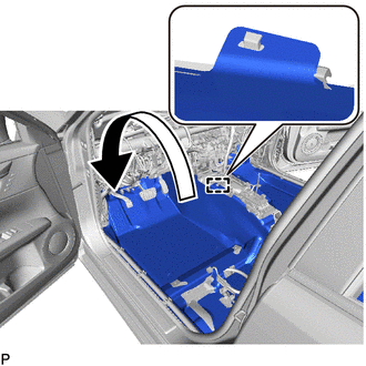
Engage the guide to install the floor carpet to the original position as shown in the illustration.
-
- Click here
INSTALL FLOOR CARPET BRACKET RH
-
Engage the 2 guides.
-
Install the floor carpet bracket RH with the 2 clips.
-
- Click here
INSTALL REAR NO. 1 AIR DUCT
-
Engage the 2 claws to install the rear No. 1 air duct.
-
- Click here
INSTALL REAR AIR DUCT GUIDE RH
-
Engage the 4 claws to install the rear air duct guide RH.
-
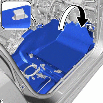
Engage the guide to install the floor carpet to the original position as shown in the illustration.
-
- Click here
INSTALL FRONT FLOOR CAUTION PLATE COVER
-
Engage the guide and claw to install the front floor caution plate cover.
-
- Click here
INSTALL FLOOR CARPET HOOK
-
Engage the 6 clamps to install the 6 floor carpet hooks.
-
Engage the 6 guides.
-
- Click here
INSTALL AIR CONDITIONING AMPLIFIER ASSEMBLY
- Click here
INSTALL ECU INTEGRATION BOX RH
for LHD: (Click here)
for RHD: (Click here)
- Click here
INSTALL WIRING HARNESS CLAMP BRACKET (for RHD)
-
Engage the claw.
-
Install the wiring harness clamp bracket with the nut.
8.0 N*m 82 kgf*cm 71 in.*lbf
-
- Click here
INSTALL INSTRUMENT PANEL JUNCTION BLOCK ASSEMBLY WITH MAIN BODY ECU
- Click here
INSTALL HYBRID VEHICLE CONTROL ECU ASSEMBLY
- Click here
INSTALL DRIVING SUPPORT ECU ASSEMBLY (w/ Pre-crash Safety System)
- Click here
INSTALL WINDSHIELD WIPER RELAY ASSEMBLY (w/ Rain Sensor)
- Click here
INSTALL STEERING POST ASSEMBLY
- Click here
INSTALL INSTRUMENT PANEL SAFETY PAD ASSEMBLY
- Click here
INSTALL STEREO COMPONENT AMPLIFIER ASSEMBLY WITH BRACKET
- Click here
INSTALL AUDIO AMPLIFIER COVER
- Click here
INSTALL FRONT SEAT ASSEMBLY LH
- Click here
INSTALL TELEMATICS TRANSCEIVER WITH MAYDAY BATTERY (w/ Telematics Transceiver)
- Click here
INSTALL AUDIO AMPLIFIER COVER (w/ Telematics Transceiver)
- Click here
INSTALL FRONT SEAT ASSEMBLY RH
Tip:Use the same procedure as for the LH side.
- Click here
CONNECT AIR CONDITIONER TUBE AND ACCESSORY ASSEMBLY
-
Remove the vinyl tape from the air conditioning tube and accessory assembly.
-
Sufficiently apply compressor oil to a new O-ring and fitting surface of the air conditioning tube and accessory assembly.
Compressor oil ND-OIL 11 or equivalent -
Install the O-ring to the air conditioning tube and accessory assembly.
-
Install the air conditioning tube and accessory assembly.
-
- Click here
CONNECT SUCTION PIPE SUB-ASSEMBLY
-
Remove the vinyl tape from the suction pipe sub-assembly.
-
Sufficiently apply compressor oil to a new O-ring and the fitting surface of the suction pipe sub-assembly.
Compressor oil ND-OIL 11 or equivalent -
Install the O-ring to the suction pipe sub-assembly.
-
Connect the suction pipe sub-assembly.
-
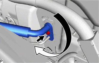
Rotate the hook connector in the direction indicated by the arrow in the illustration.
-
Insert the pipe joint into the fitting hole securely and tighten the bolt.
9.8 N*m 100 kgf*cm 87 in.*lbf
-
- Click here
CONNECT HEATER INLET WATER HOSE
-
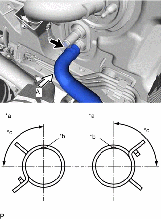
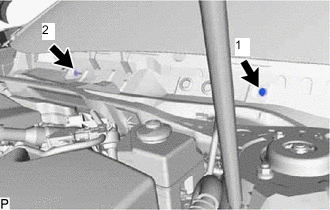
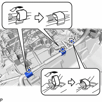
Connect the heater inlet water hose with the marking (blue) facing up and engage the clip within the area shown in the illustration.
Table 6. Text in Illustration *a View A *b Heater Inlet Water Hose Marking (Blue) *c Clip installation angle (75 to 105°) Note:Do not apply excessive force to the heater inlet water hose.
-
- Click here
CONNECT HEATER OUTLET WATER HOSE
-
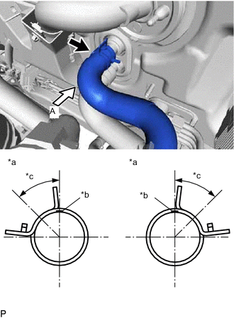
Connect the heater outlet water hose with the marking (orange) facing up and engage the clip within the area shown in the illustration.
Table 7. Text in Illustration *a View A *b Heater Outlet Water Hose (Orange) *c Clip installation angle (30 to 60°) Note:Do not apply excessive force to the heater outlet water hose.
-
- Click here
CONNECT NO. 1 BRAKE ACTUATOR TUBE
-
Connect the No. 1 brake actuator tube with the nut.
5.4 N*m 55 kgf*cm 48 in.*lbf
-
- Click here
INSTALL FRONT OUTER COWL TOP PANEL SUB-ASSEMBLY
for LHD: (Click here)
for RHD: (Click here)
- Click here
INSTALL WINDSHIELD WIPER MOTOR AND LINK ASSEMBLY
- Click here
ADD COOLANT (for Engine)
- Click here
INSPECT FOR COOLANT LEAK (for Engine)
- Click here
CHARGE AIR CONDITIONING SYSTEM WITH REFRIGERANT
- Click here
WARM UP COMPRESSOR
- Click here
INSPECT FOR REFRIGERANT LEAK
- Click here
INITIALIZE SERVO MOTOR
- Click here
INSPECT SHIFT LEVER POSITION (for LHD)