AIR CONDITIONING UNIT INSTALLATION
PROCEDURE
-
INSTALL DRAIN COOLER HOSE
-
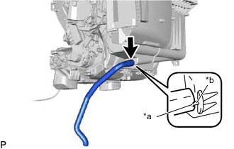
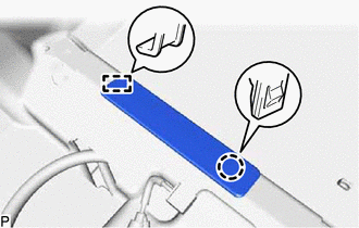
Text in Illustration *a Hose Notch *b Rib Align the hose notch and rib as shown in the illustration and install the drain cooler hose.
-
-
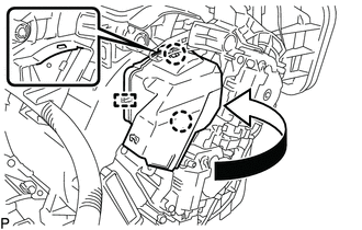
INSTALL ASPIRATOR PIPE
-
Engage the 2 claws to install the aspirator pipe.
-
-
INSTALL COOLER THERMISTOR HOSE
-
Install the cooler thermistor hose.
-
Engage the clamp.
-
-
INSTALL HEATER PACKING
-
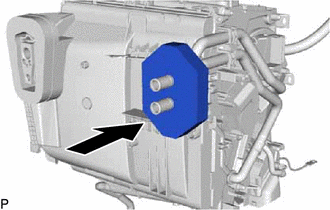
Install the heater packing as shown in the illustration.
-
-
INSTALL NO. 4 AIR DUCT SUB-ASSEMBLY (for RHD)
-
Engage the guide and 2 claws to install the No. 4 air duct sub-assembly as shown in the illustration.
-
-
INSTALL NO. 1 AIR DUCT SUB-ASSEMBLY
-
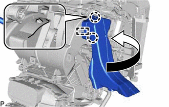
Engage the guide and 2 claws to install the No. 1 air duct sub-assembly as shown in the illustration.
-
-
INSTALL NO. 6 HEATER TO REGISTER DUCT ASSEMBLY
-
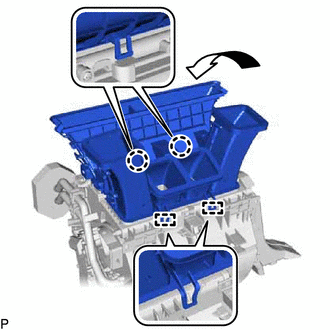
Engage the 2 guides and 2 claws to install the No. 6 heater to register duct assembly as shown in the illustration.
-
-
INSTALL AIR CONDITIONING HARNESS ASSEMBLY
-
Engage each clamp to install the air conditioning harness assembly.
-
Connect each connector.
-
-
INSTALL BLOWER ASSEMBLY
for LHD: Click here
for RHD: Click here
-
INSTALL AIR CONDITIONING UNIT ASSEMBLY
-
Install the air conditioning unit assembly to the instrument panel reinforcement assembly with the 3 bolts.
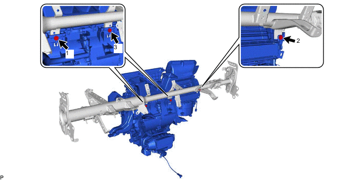
- Torque:
- 9.8 N*m { 100 kgf*cm, 87 in.*lbf }
Note
Tighten the bolts in the order shown in the illustration to install the air conditioning unit assembly.
-
-
INSTALL INSTRUMENT PANEL REINFORCEMENT ASSEMBLY WITH AIR CONDITIONING UNIT
Note
-
Be sure to support the air conditioning unit assembly when installing it because failure to do so may cause the bracket of the air conditioning unit assembly to break.
-
When installing the air conditioning unit, eliminate static electricity by touching the vehicle body to prevent the components from being damaged.
-
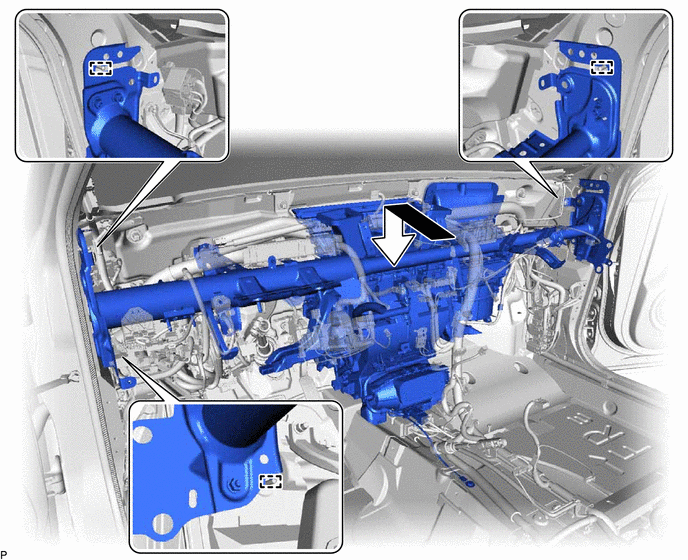
Engage the 3 guides and temporarily install the instrument panel reinforcement assembly with air conditioning unit as shown in the illustration.
-
Install the instrument panel reinforcement assembly with the 3 bolts <A> and 2 new bolts <B> in the order shown in the illustration.
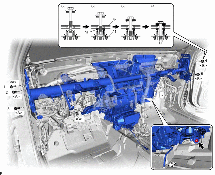
Text in Illustration *1 Instrument Panel Reinforcement Assembly - - *a Movable Collar *b Body *c Step 1 *d Step 2 *e Step 3 *f Step 4 - Torque:
- 20 N*m { 204 kgf*cm, 15 ft.*lbf }
Note
Tighten the bolts in the order shown in the illustration to install the reinforcement assembly.
-
Install the bolt <C>.
- Torque:
- 15 N*m { 153 kgf*cm, 11 ft.*lbf }
-
Install the instrument panel reinforcement assembly with air conditioning unit with the nut.
- Torque:
- 9.8 N*m { 100 kgf*cm, 87 in.*lbf }
-
Pass the drain cooler hose through the vehicle securely.
Note
Connect the cooler drain hose firmly to prevent water leaks.
-
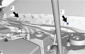
Install the 2 bolts.
- Torque:
- 9.8 N*m { 100 kgf*cm, 87 in.*lbf }
Note
Tighten the bolts in the order shown in the illustration.
-
Install the 2 hole plugs.
-
for LHD:
-
Engage each clamp.
-
Connect the connector.
-
Connect the 4 earth wires with the 4 bolts.
- Torque:
- 8.4 N*m { 86 kgf*cm, 74 in.*lbf }
-
Connect the protector with the nut.
- Torque:
- 8.0 N*m { 82 kgf*cm, 71 in.*lbf }
-
Connect the connector holder with the 2 nuts.
- Torque:
- 8.0 N*m { 82 kgf*cm, 71 in.*lbf }
-
-
for RHD:
-
Engage each clamp.
-
Connect the connector.
-
Connect the 4 earth wires with the 4 bolts.
- Torque:
- 8.4 N*m { 86 kgf*cm, 74 in.*lbf }
-
Connect the connector holder with the 2 nuts.
- Torque:
- 8.0 N*m { 82 kgf*cm, 71 in.*lbf }
-
-
Engage the claw to connect the airbag connector as shown in the illustration.
-
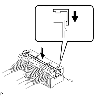
Text in Illustration *a Retainer Engage the 2 claws to lock the retainer as shown in the illustration.
-
Connect the connector.
-
Install the bolt.
- Torque:
- 20 N*m { 199 kgf*cm, 14 ft.*lbf }
-
for LHD:
-
Install the shift lever support Click here.
-
Install the lower shift lever assembly Click here.
-
-
Engage each clamp.
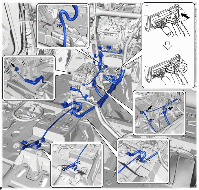
Text in Illustration *1 Airbag Sensor Assembly - - -
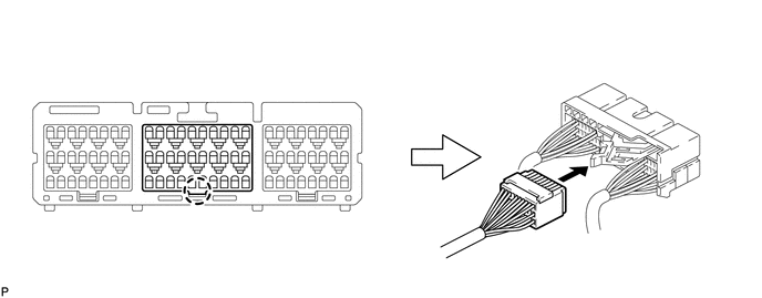
Connect each connector.
-
Connect the connector to the airbag sensor assembly as shown in the illustration.
Note
When connecting any airbag connector, take care not to damage the airbag wire harness.
-
Engage the 3 claws to close the 3 clamps as shown in the illustration.
-
w/ Telematics Transceiver:
-
Engage each clamp.
-
-
Engage each clamp.
-
-
INSTALL INSTRUMENT PANEL SAFETY PAD CAP
-
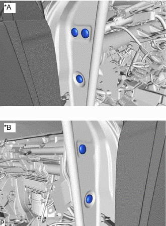
Text in Illustration *A for LH Side *B for RH Side Install 5 new instrument panel safety pad caps.
-
-
INSTALL NO. 1 HEATER TO REGISTER DUCT
-
Install the No. 1 heater to register duct with the 3 clips.
-
Engage the clamp.
-
-
INSTALL NO. 2 INSTRUMENT PANEL BRACE SUB-ASSEMBLY
-
Install the No. 2 instrument panel brace sub-assembly with the bolt and 2 nuts.
- Torque:
- 20 N*m { 204 kgf*cm, 15 ft.*lbf }
-
Install the screw.
-
Engage each clamp.
-
Connect the connector.
-
Connect the earth wire with the bolt.
- Torque:
- 8.4 N*m { 86 kgf*cm, 74 in.*lbf }
-
-
INSTALL NO. 1 INSTRUMENT PANEL BRACE SUB-ASSEMBLY
-
Install the No. 1 instrument panel brace sub-assembly with the bolt and 2 nuts.
- Torque:
- 20 N*m { 204 kgf*cm, 15 ft.*lbf }
-
Install the screw.
-
Engage the clamp.
-
Connect the connector.
-
-
INSTALL COOLER (ROOM TEMP. SENSOR) THERMISTOR
-
Connect the cooler thermistor hose and connector to install the cooler (room temp. sensor) thermistor.
-
-
INSTALL NO. 1 CONSOLE BOX DUCT
-
Install the No. 1 console box duct with the clip.
-
-
INSTALL NO. 1 CONSOLE BOX MOUNTING BRACKET (for LHD)
-
INSTALL FLOOR CARPET BRACKET LH
-
Engage the 2 guides.
-
Install the floor carpet bracket LH with the 2 clips.
-
-
INSTALL REAR NO. 2 AIR DUCT
-
Engage the 2 claws to install the rear No. 2 air duct.
-
-
INSTALL REAR AIR DUCT GUIDE LH
-
Engage the 4 claws to install the rear air duct guide LH.
-
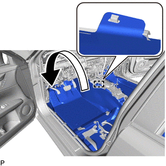
Engage the guide to install the floor carpet to the original position as shown in the illustration.
-
-
INSTALL FLOOR CARPET BRACKET RH
-
Engage the 2 guides.
-
Install the floor carpet bracket RH with the 2 clips.
-
-
INSTALL REAR NO. 1 AIR DUCT
-
Engage the 2 claws to install the rear No. 1 air duct.
-
-
INSTALL REAR AIR DUCT GUIDE RH
-
Engage the 4 claws to install the rear air duct guide RH.
-
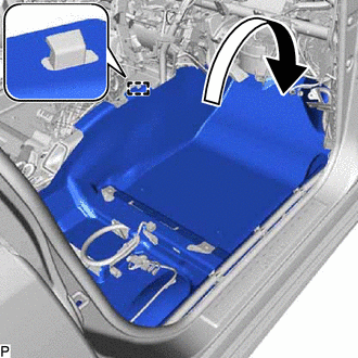
Engage the guide to install the floor carpet to the original position as shown in the illustration.
-
-
INSTALL FRONT FLOOR CAUTION PLATE COVER
-
Engage the guide and claw to install the front floor caution plate cover.
-
-
INSTALL FLOOR CARPET HOOK
-
Engage the 6 clamps to install the 6 floor carpet hooks.
-
Engage the 6 guides.
-
-
INSTALL AIR CONDITIONING AMPLIFIER ASSEMBLY
-
INSTALL ECU INTEGRATION BOX RH
for LHD: Click here
for RHD: Click here
-
INSTALL WIRING HARNESS CLAMP BRACKET (for RHD)
-
Engage the claw.
-
Install the wiring harness clamp bracket with the nut.
- Torque:
- 8.0 N*m { 82 kgf*cm, 71 in.*lbf }
-
-
INSTALL INSTRUMENT PANEL JUNCTION BLOCK ASSEMBLY WITH MAIN BODY ECU
-
INSTALL POWER MANAGEMENT CONTROL ECU
-
INSTALL DRIVING SUPPORT ECU ASSEMBLY (w/ Dynamic Radar Cruise Control System)
for RHD: Click here
-
INSTALL SEAT BELT CONTROL ECU (w/ Pre-crash Safety System)
-
INSTALL WINDSHIELD WIPER RELAY ASSEMBLY (w/ Rain Sensor)
-
INSTALL STEERING POST ASSEMBLY
-
INSTALL INSTRUMENT PANEL SAFETY PAD ASSEMBLY
-
INSTALL STEREO COMPONENT AMPLIFIER ASSEMBLY WITH BRACKET
-
INSTALL AUDIO AMPLIFIER COVER
-
INSTALL FRONT SEAT ASSEMBLY LH
-
INSTALL TELEMATICS TRANSCEIVER WITH MAYDAY BATTERY (w/ Telematics Transceiver)
-
INSTALL AUDIO AMPLIFIER COVER (w/ Telematics Transceiver)
-
INSTALL FRONT SEAT ASSEMBLY RH
Tech Tips
Use the same procedure as for the LH side.
-
CONNECT AIR CONDITIONER TUBE AND ACCESSORY ASSEMBLY
-
Remove the vinyl tape from the air conditioning tube and accessory assembly.
-
Sufficiently apply compressor oil to a new O-ring and fitting surface of the air conditioning tube and accessory assembly.
Compressor oil ND-OIL 11 or equivalent -
Install the O-ring to the air conditioning tube and accessory assembly.
-
Install the air conditioning tube and accessory assembly.
-
-
CONNECT SUCTION PIPE SUB-ASSEMBLY
-
Remove the vinyl tape from the suction pipe sub-assembly.
-
Sufficiently apply compressor oil to a new O-ring and the fitting surface of the suction pipe sub-assembly.
Compressor oil ND-OIL 11 or equivalent -
Install the O-ring to the suction pipe sub-assembly.
-
Connect the suction pipe sub-assembly.
-
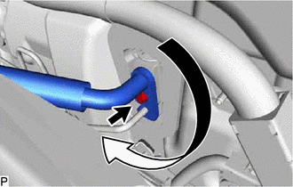
Rotate the hook connector in the direction indicated by the arrow in the illustration.
-
Insert the pipe joint into the fitting hole securely and tighten the bolt.
- Torque:
- 9.8 N*m { 100 kgf*cm, 87 in.*lbf }
-
-
CONNECT HEATER INLET WATER HOSE
-
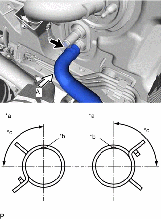
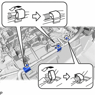
Text in Illustration *a View A *b Heater Inlet Water Hose Marking (Blue) *c Clip installation angle (75 to 105°) Connect the heater inlet water hose with the marking (blue) facing up and engage the clip within the area shown in the illustration.
Note
Do not apply excessive force to the heater inlet water hose.
-
-
CONNECT HEATER OUTLET WATER HOSE
-
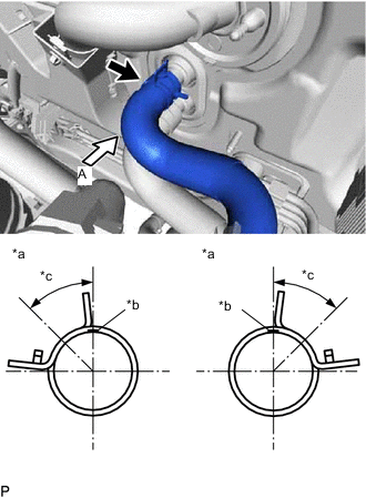
Text in Illustration *a View A *b Heater Outlet Water Hose (Orange) *c Clip installation angle (30 to 60°) Connect the heater outlet water hose with the marking (orange) facing up and engage the clip within the area shown in the illustration.
Note
Do not apply excessive force to the heater outlet water hose.
-
-
CONNECT NO. 1 BRAKE ACTUATOR TUBE
-
Connect the No. 1 brake actuator tube with the nut.
- Torque:
- 5.4 N*m { 55 kgf*cm, 48 in.*lbf }
-
-
INSTALL FRONT OUTER COWL TOP PANEL SUB-ASSEMBLY
for LHD: Click here
for RHD: Click here
-
INSTALL WINDSHIELD WIPER MOTOR AND LINK ASSEMBLY
-
ADD COOLANT (for Engine)
-
INSPECT FOR COOLANT LEAK (for Engine)
-
CHARGE AIR CONDITIONING SYSTEM WITH REFRIGERANT
-
WARM UP COMPRESSOR
-
INSPECT FOR REFRIGERANT LEAK
-
INITIALIZE SERVO MOTOR
-
INSPECT SHIFT LEVER POSITION (for LHD)