| DTC Code | DTC Name |
|---|---|
| Blower Motor Circuit |
DESCRIPTION
The blower motor with fan sub-assembly is operated by signals from the air conditioning amplifier assembly. Blower motor speed signals are transmitted in accordance with changes in the duty ratio.
WIRING DIAGRAM
CAUTION / NOTICE / HINT
Inspect the fuses for circuits related to this system before performing the following inspection procedure.
PROCEDURE
- Click here
PERFORM ACTIVE TEST USING GTS
-
Connect the GTS to the DLC3.
-
Turn the power switch on (IG).
-
Turn the GTS on.
-
Enter the following menus: Body Electrical / Air Conditioner / Active Test.
-
Check the operation by referring to the table below.
Table 2. Air Conditioner Tester Display Test Part Control Range Diagnostic Note Blower Motor blower motor with fan sub-assembly Min.: 0, Max.: 31 - Result Result Proceed to OK A NG (blower motor does not operate) B NG (blower motor operates but does not change speed) C
- A
PROCEED TO NEXT SUSPECTED AREA SHOWN IN PROBLEM SYMPTOMS TABLE (Click here)
- BClick here
- CClick here
-
- Click here
CHECK HARNESS AND CONNECTOR (BLOWER MOTOR WITH FAN SUB-ASSEMBLY - BODY GROUND)
-
Disconnect the H53 blower motor with fan sub-assembly connector.
-
Measure the resistance according to the value(s) in the table below.
Standard Resistance Tester Connection Condition Specified Condition H53-1 (GND) - Body ground Always Below 1 Ω
- OKClick here
- NG
REPAIR OR REPLACE HARNESS OR CONNECTOR
-
- Click here
CHECK HARNESS AND CONNECTOR (BLOWER MOTOR WITH FAN SUB-ASSEMBLY - POWER SOURCE)
-
Measure the voltage according to the value(s) in the table below.
Standard Voltage Tester Connection Condition Specified Condition H53-3 (+B) - Body ground Power switch off 11 to 14 V
- OKClick here
- NG
REPAIR OR REPLACE HARNESS OR CONNECTOR
-
- Click here
CHECK HARNESS AND CONNECTOR (AIR CONDITIONING AMPLIFIER ASSEMBLY - BLOWER MOTOR WITH FAN SUB-ASSEMBLY)
-
Disconnect the H54 air conditioning amplifier assembly connector.
-
Measure the resistance according to the value(s) in the table below.
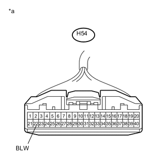
Standard Resistance Tester Connection Condition Specified Condition H54-22 (BLW) - H53-2 (SI) Always Below 1 Ω H54-22 (BLW) - Body ground Always 10 kΩ or higher
- OKClick here
- NG
REPAIR OR REPLACE HARNESS OR CONNECTOR
-
- Click here
INSPECT BLOWER MOTOR WITH FAN SUB-ASSEMBLY
-
Reconnect the H53 blower motor with fan sub-assembly connector.
-
Measure the voltage according to the value(s) in the table below.
Standard Voltage Tester Connection Condition Specified Condition H54-22 (BLW) - Body ground Power switch off 4.5 to 5.5 V Table 3. Text in Illustration *a Front view of wire harness connector
(to Air Conditioning Amplifier Assembly)
- OKClick here
- NG
REPLACE BLOWER MOTOR WITH FAN SUB-ASSEMBLY (Click here)
-
- Click here
INSPECT AIR CONDITIONING AMPLIFIER ASSEMBLY
-
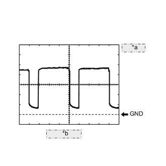
Table 4. *a 1 V/DIV. *b 500 μs./DIV. 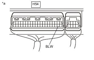
Remove the air conditioning amplifier assembly (Click here).
-
Reconnect the H54 air conditioning amplifier assembly connector.
-
Turn the power switch on (IG).
-
Turn the blower switch on (LO).
-
Measure the waveform between terminal H54-22 (BLW) of the air conditioning amplifier assembly and body ground.
OK Waveform is similar to that shown in the illustration. Tip:The waveform varies with the blower speed.
Item Content Tool setting 1 V/DIV., 500 μs./DIV. Vehicle condition Power switch on (IG)
Blower switch LO
Table 5. Text in Illustration *a Component with harness connected
(Air Conditioning Amplifier Assembly)
- OK
REPLACE BLOWER MOTOR WITH FAN SUB-ASSEMBLY (Click here)
- NG
REPLACE AIR CONDITIONING AMPLIFIER ASSEMBLY (Click here)
-