ГЕНЕРАТОР (для моделей с номинальным током 100 A) СНЯТИЕ

-
REMOVE FRONT DRIVE SHAFT ASSEMBLY RH
-
REMOVE BATTERY SERVICE HOLE COVER
-
Remove the clip and battery service hole cover.
-
-
PRECAUTION
Note
After turning the ignition switch off, waiting time may be required before disconnecting the cable from the battery terminal. Therefore, make sure to read the disconnecting the cable from the battery terminal notice before proceeding with work Click here.
-
DISCONNECT CABLE FROM NEGATIVE BATTERY TERMINAL
Note
When disconnecting the cable, some systems need to be initialized after the cable is reconnected Click here.
-
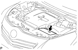
REMOVE NO. 1 ENGINE COVER
-
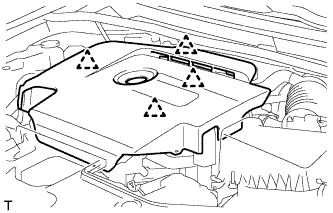
Hold the rear of the cover and slowly raise it to detach the clip on the rear of the cover. Continue to raise the cover to detach the 3 clips on the front and side of the cover and remove the cover.
Note
Attempting to disengage both front and rear clips at the same time may cause the cover to break.
-
-
REMOVE RADIATOR SUPPORT OPENING COVER
-
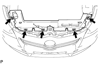
Remove the 5 clips and radiator support opening cover.
-
-
REMOVE NO. 1 ENGINE UNDER COVER
-
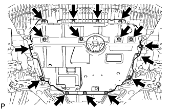
Remove the 6 bolts and 10 clips.
-
Remove the No. 1 engine under cover.
-
-
REMOVE REAR ENGINE UNDER COVER RH
-
Remove the 5 clips and under cover.
-
-
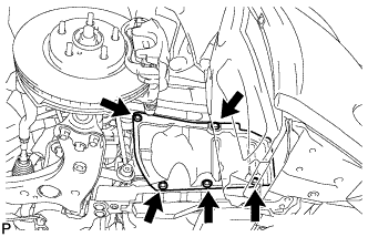
REMOVE FRONT SUSPENSION MEMBER REINFORCEMENT RH
-
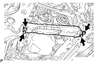
Выверните 4 болта и снимите правое усиление элемента передней подвески.
-
-
REMOVE FAN AND GENERATOR V BELT
-
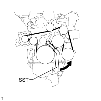
Using SST and a 22 mm wrench, rotate the tensioner pulley counterclockwise to loosen the belt tension. Then remove the belt.
- SST
- 09216-42010
CAUTION:
-
Be careful as the wrench only fits loosely on the belt tensioner tool set point. The wrench may come off the set point and cause injuries.
-
Be careful that your hands do not become jammed between parts such as the belt, pulleys, etc.
Note
Make sure SST is installed as shown in the illustration. If not, SST and/or the belt may not be able to be removed.
-
-
REMOVE GENERATOR ASSEMBLY
-
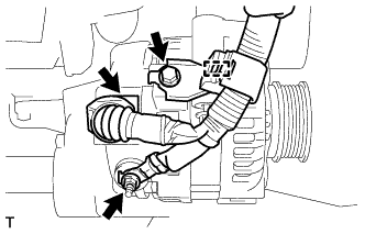
Remove the terminal cap.
-
Disconnect the generator connector and detach the clamp.
-
Remove the nut and bolt, and disconnect the generator wire.
-
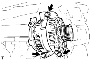
Remove the 3 bolts and generator.
-