КОРПУС ДИФФЕРЕНЦИАЛА ПОВТОРНАЯ СБОРКА

-
INSTALL FRONT DIFFERENTIAL SIDE GEAR
-
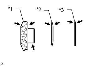
Text in Illustration *1 Front Differential Side Gear *2 Conical Spring *3 front differential side gear thrust washer 
Gear Oil Apply gear oil to the front differential side gear, front differential side gear thrust washer and conical spring
-
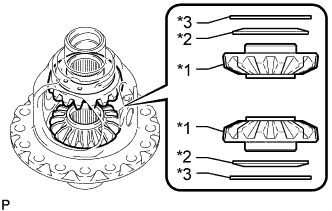
Text in Illustration *1 Front Differential Side Gear *2 Conical Spring *3 front differential side gear thrust washer Install the 2 front differential side gears, 2 front differential side gear thrust washers and 2 conical springs to the front No. 1 differential case sub-assembly.
Note
-
Do not drop the front differential side gear, front differential side gear thrust washer and conical spring.
-
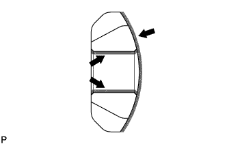
Make sure that the conical spring is installed in the correct direction.
-
-
Set SST as shown in the illustration and tighten it.
- SST
- 09528-52010 ( 09953-05010, 09528-05010 )
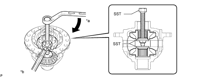
Text in Illustration *a Turn *b Hold Tech Tips
-
Tighten SST until the front differential pinion can enter the front No. 1 differential case sub-assembly.
-
When installing the front differential pinion, do not overtighten SST, as it is necessary to rotate the front differential side gear.
-
Apply gear oil to the front differential pinion thrust washer.
Text in Illustration Gear Oil -
Apply gear oil to the front differential pinion.
Text in Illustration Gear Oil -
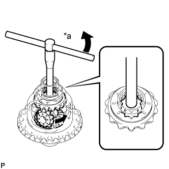
Text in Illustration *a Turn Using SST as shown in the illustration, rotate the front differential side gear and install the 2 front differential pinions and 2 front differential pinion thrust washers.
- SST
- 09528-52010 ( 09528-05030 )
CAUTION:
Be careful not to catch your fingers between the front differential pinion and front No. 1 differential case sub-assembly.
Note
Do not drop the front differential pinion and front differential pinion thrust washer.
-
-
INSPECT FRONT DIFFERENTIAL PINION BACKLASH
-
Set SST as shown in the illustration and tighten it.
- SST
- 09528-52010 ( 09953-05010, 09528-05010 )
- Torque:
- 10 N*m { 102 kgf*cm, 8 ft.*lbf }
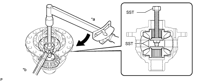
Text in Illustration *a Turn *b Hold -
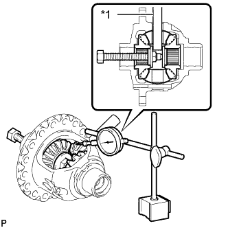
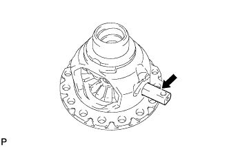
Text in Illustration *1 Front No. 1 Differential Pinion Shaft Install the front No. 1 differential pinion shaft to the front differential pinion as shown in the illustration.
-
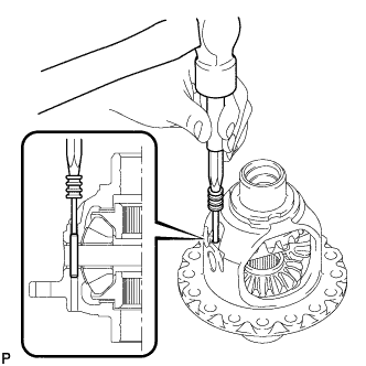
Using a dial indicator, measure the front differential pinion backlash.
Standard backlash 0.15 mm (0.00590 in.) or less If the backlash is not as specified, replace the front differential side gear thrust washers with washers of a different thickness. Use the table below to select a front differential side gear thrust washer which will ensure that the backlash is within the specification.
Thrust Washer Thickness Specified Condition Specified Condition 1.25 mm (0.0492 in.) 1.65 mm (0.0650 in.) 1.30 mm (0.0512 in.) 1.70 mm (0.0669 in.) 1.35 mm (0.0531 in.) 1.75 mm (0.0689 in.) 1.40 mm (0.0551 in.) 1.80 mm (0.0709 in.) 1.45 mm (0.0571 in.) 1.85 mm (0.0728 in.) 1.50 mm (0.0591 in.) 1.90 mm (0.0748 in.) 1.55 mm (0.0610 in.) 1.95 mm (0.0768 in.) 1.60 mm (0.0630 in.) - Tech Tips
Select washers of the same thickness for both the right and left sides.
-
-
INSTALL FRONT NO. 1 DIFFERENTIAL PINION SHAFT
-
Apply gear oil to the front No. 1 differential pinion shaft.
Text in Illustration Gear Oil -
Install the front No. 1 differential pinion shaft to the front No. 1 differential case sub-assembly so that the hole for the front differential pinion shaft straight pin is aligned with the hole in the front No. 1 differential case sub-assembly.
-
-
INSPECT FRONT NO. 1 DIFFERENTIAL CASE SUB-ASSEMBLY
-
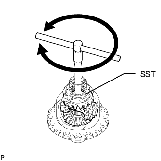
Using SST, rotate the front differential side gear as shown in the illustration.
- SST
- 09528-52010 ( 09528-05030 )
Standard The gear does not lock when rotated in either direction.
-
If the front differential side gear locks, perform all remaining inspection procedures.
-
Replace any parts that do not meet the specifications.
-
If the front differential side gear locks after performing the inspection procedures again, replace the front No. 1 differential case assembly.
-
-
INSTALL FRONT DIFFERENTIAL PINION SHAFT STRAIGHT PIN
-
Using a 5 mm pin punch and hammer, tap in the front differential pinion shaft straight pin to the front No. 1 differential case sub-assembly.
-
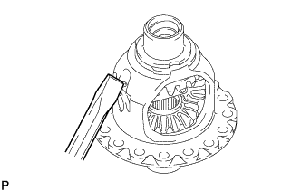
Using a chisel and hammer, stake the front No. 1 differential case sub-assembly.
-
-
INSTALL FRONT DIFFERENTIAL RING GEAR
-
Clean the contact surfaces of the front No. 1 differential case sub-assembly and front differential ring gear.
-
Using a heater, heat the front differential ring gear to 90 to 110°C (194 to 230°F) in boiling water.
-
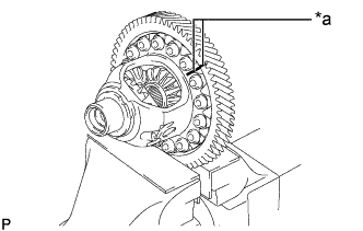
Text in Illustration *a Matchmark After the moisture on the front differential ring gear has completely evaporated, quickly align the matchmarks on the front differential ring gear and the front No. 1 differential case sub-assembly and install the front differential ring gear to the front No. 1 differential case sub-assembly.
-
Install the 16 bolts.
- Torque:
- 106 N*m { 1081 kgf*cm, 78 ft.*lbf }
-
-
INSTALL FRONT DIFFERENTIAL CASE FRONT TAPERED ROLLER BEARING
-

Using SST and a press, press in a new front differential case front tapered roller bearing.
- SST
- 09523-36010
- 09950-60010 ( 09951-00460, 09951-00560, 09952-06010 )
- 09950-70010 ( 09951-07150 )
-
-
INSTALL FRONT DIFFERENTIAL CASE REAR TAPERED ROLLER BEARING
-

Using SST and a press, press in a new front differential case rear tapered roller bearing.
- SST
- 09554-22010
-