ВАЛ РЫЧАГА ВЫБОРА И ПЕРЕКЛЮЧЕНИЯ ПЕРЕДАЧ ПОВТОРНАЯ СБОРКА

-
INSTALL CONTROL SHAFT COVER OIL SEAL
-
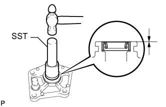
Using SST and a hammer, install a new control shaft cover oil seal to the control shaft cover.
- SST
- 09307-12010
Standard depth 0 to 0.5 mm (0 to 0.0196 in.) -
Coat the lip of the oil seal with MP grease.
-
-
INSTALL SHIFT LEVER DAMPER
-
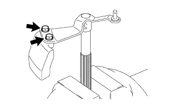
Coat the 2 bolts with adhesive.
Adhesive Toyota Genuine Adhesive 1344, Three Bond 1344 or equivalent -
Install the shift lever damper to the shift and select lever shaft with the 2 bolts.
- Torque:
- 19 N*m { 190 kgf*cm, 14 ft.*lbf }
-
-
INSTALL PIN
-
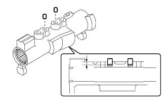
Install the 2 pins to the inner No. 1 shift lever.
Standard depth 3.5 to 4.5 mm (0.138 to 0.177 in.)
-
-
INSTALL SHIFT GATE PLATE
-
Install the shift gate plate with the 2 bolts.
- Torque:
- 8.5 N*m { 87 kgf*cm, 75 in.*lbf }
-
-
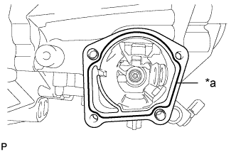
INSTALL SHIFT AND SELECT LEVER SHAFT
-
Coat the shift and select lever boot lip and shift and select lever shaft with MP grease.
-
Install the shift and select lever boot and control shaft cover to the shift and select lever shaft.
-
-
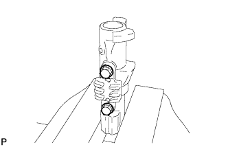
INSTALL INNER NO. 1 SHIFT LEVER
-
Coat the shift interlock plate with MP grease.
-
Install the inner No. 1 shift lever and shift interlock plate to the shift and select lever shaft.
-
Using a 5 mm pin punch and hammer, tap the slotted spring pin into the inner No. 1 shift lever.
Standard depth 0.4 to 1.4 mm (0.0158 to 0.0551 in.)
-
-
INSTALL SHIFT AND SELECT LEVER ASSEMBLY
-
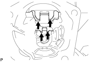
Align the 4 shift fork shafts as shown in the illustration.
-
Apply seal packing to the manual transmission case as shown in the illustration.
Seal packing Toyota Genuine Seal Packing 1281, Three Bond 1281 or equivalent Text in Illustration *a Seal Packing Note
Assemble parts within 10 minutes of application. Otherwise, the packing (FIPG) material must be removed and reapplied.
-
Coat the 4 bolts with adhesive.
Adhesive Toyota Genuine Adhesive 1344, Three Bond 1344 or equivalent -
Install the shift and select lever assembly to the manual transmission case with the 4 bolts.
- Torque:
- 19 N*m { 190 kgf*cm, 14 ft.*lbf }
-
-
INSTALL SHIFT GATE PIN
-
Coat the shift gate pin with adhesive.
Adhesive Toyota Genuine Adhesive 1344, Three Bond 1344 or equivalent -
Install the shift gate pin to the manual transmission case.
- Torque:
- 30 N*m { 306 kgf*cm, 22 ft.*lbf }
-
-
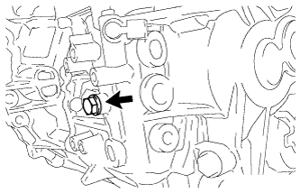
INSTALL NO. 2 LOCK BALL ASSEMBLY
-
Coat the No. 2 lock ball with adhesive.
Adhesive Toyota Genuine Adhesive 1344, Three Bond 1344 or equivalent -
Install the No. 2 lock ball to the manual transmission case.
- Torque:
- 29 N*m { 300 kgf*cm, 22 ft.*lbf }
-
-
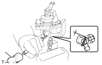
INSTALL NEUTRAL POSITION SWITCH (w/ Stop And Start System)
-
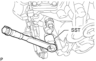
Using SST, install a new gasket and the neutral position switch to the manual transaxle assembly.
- SST
- 09817-16011
- Torque:
- 40 N*m { 410 kgf*cm, 30 ft.*lbf }
-
Connect the neutral position switch connector.
-
-
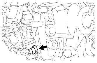
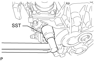
INSTALL NO. 1 LOCK BALL ASSEMBLY
-
Coat the No. 1 lock ball with adhesive.
Adhesive Toyota Genuine Adhesive 1344, Three Bond 1344 or equivalent -
Install the No. 1 lock ball to the manual transmission case.
- Torque:
- 39 N*m { 400 kgf*cm, 29 ft.*lbf }
-
-
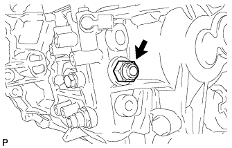
INSTALL BACK-UP LIGHT SWITCH ASSEMBLY
-
Using SST, install a new gasket and the back-up light switch to the manual transmission case.
- SST
- 09816-30010
- Torque:
- 40 N*m { 410 kgf*cm, 30 ft.*lbf }
-
-
INSTALL NO. 1 SELECTING BELLCRANK DUST COVER
-
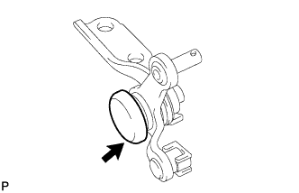
Install the No. 1 selecting bellcrank dust cover to the selecting bellcrank.
-
-
INSTALL CONTROL SHIFT LEVER BUSHING
-
Install the control shift lever bushing to the selecting bellcrank.
-
-
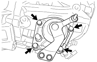
INSTALL SHIFT SELECTING BELLCRANK ASSEMBLY
-
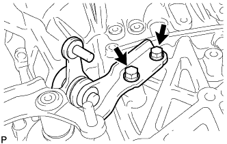
Install the selecting bellcrank assembly to the manual transmission case with the 2 bolts.
- Torque:
- 20 N*m { 204 kgf*cm, 15 ft.*lbf }
-