ВЫХОДНОЙ ВАЛ РАЗБОРКА

-
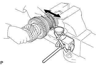
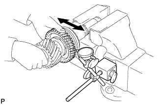
INSPECT 1ST DRIVEN GEAR THRUST CLEARANCE
-
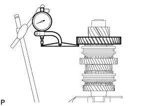
Using a dial indicator, measure the 1st driven gear thrust clearance.
Standard clearance 0.10 to 0.35 mm (0.00394 to 0.0137 in.) Maximum clearance 0.35 mm (0.0137 in.) If the clearance is more than the maximum, replace the 1st driven gear, needle roller bearing or output shaft. Replace the part or parts determined to be the most likely cause of the problem.
-
-
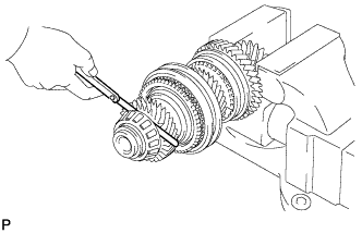
INSPECT 1ST DRIVEN GEAR RADIAL CLEARANCE
-
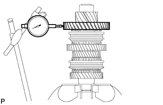
Using a dial indicator, measure the 1st driven gear radial clearance.
Standard clearance 0.015 to 0.068 mm (0.000591 to 0.00267 in.) Maximum clearance 0.068 mm (0.00267 in.) If the clearance is more than the maximum, replace the 1st driven gear, needle roller bearing or output shaft. Replace the part or parts determined to be the most likely cause of the problem.
-
-
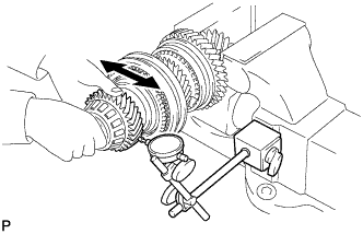
INSPECT 2ND DRIVEN GEAR THRUST CLEARANCE
-
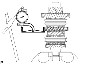
Using a dial indicator, measure the 2nd driven gear thrust clearance.
Standard clearance 0.11 to 0.46 mm (0.00434 to 0.0181 in.) Maximum clearance 0.46 mm (0.0181 in.) If the clearance is more than the maximum, replace the 2nd driven gear, needle roller bearing or output shaft. Replace the part or parts determined to be the most likely cause of the problem.
-
-
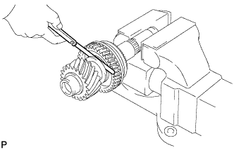
INSPECT 2ND DRIVEN GEAR RADIAL CLEARANCE
-
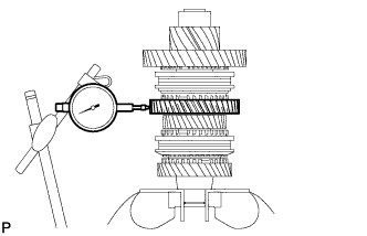
Using a dial indicator, measure the 2nd driven gear radial clearance.
Standard clearance 0.015 to 0.048 mm (0.000591 to 0.00188 in.) Maximum clearance 0.048 mm (0.00188 in.) If the clearance is more than the maximum, replace the 2nd driven gear, needle roller bearing or output shaft. Replace the part or parts determined to be the most likely cause of the problem.
-
-
INSPECT 3RD DRIVEN GEAR THRUST CLEARANCE
-
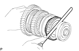
Using a feeler gauge, measure the 3rd driven gear thrust clearance.
Standard clearance 0.11 to 0.54 mm (0.00434 to 0.0212 in.) Maximum clearance 0.54 mm (0.0212 in.) If the clearance is more than the maximum, replace the 3rd driven gear, needle roller bearing or output shaft. Replace the part or parts determined to be the most likely cause of the problem.
-
-
INSPECT 3RD DRIVEN GEAR RADIAL CLEARANCE
-
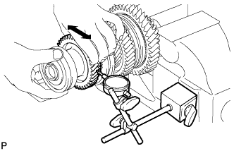
Using a dial indicator, measure the 3rd driven gear radial clearance.
Standard clearance 0.015 to 0.066 mm (0.000591 to 0.00259 in.) Maximum clearance 0.066 mm (0.00259 in.) If the clearance is more than the maximum, replace the 3rd driven gear, needle roller bearing or output shaft. Replace the part or parts determined to be the most likely cause of the problem.
-
-
INSPECT 4TH DRIVEN GEAR THRUST CLEARANCE
-
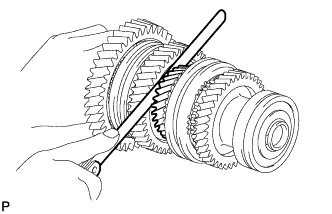
Using a feeler gauge, measure the 4th driven gear thrust clearance.
Standard clearance 0.10 to 0.65 mm (0.00394 to 0.0255 in.) Maximum clearance 0.65 mm (0.0255 in.) If the clearance is more than the maximum, replace the 4th driven gear, needle roller bearing or output shaft. Replace the part or parts determined to be the most likely cause of the problem.
-
-
INSPECT 4TH DRIVEN GEAR RADIAL CLEARANCE
-
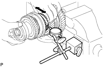
Using a dial indicator, measure the 4th driven gear radial clearance.
Standard clearance 0.015 to 0.066 mm (0.000591 to 0.00259 in.) Maximum clearance 0.066 mm (0.00259 in.) If the clearance is more than the maximum, replace the 4th driven gear, needle roller bearing or output shaft. Replace the part or parts determined to be the most likely cause of the problem.
-
-
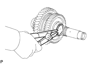
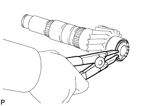
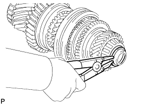
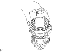
REMOVE OUTPUT SHAFT BEARING SHAFT SNAP RING
-
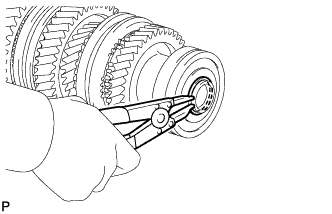
Using a snap ring expander, remove the output shaft bearing shaft snap ring from the No. 1 output shaft.
-
-
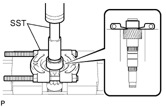
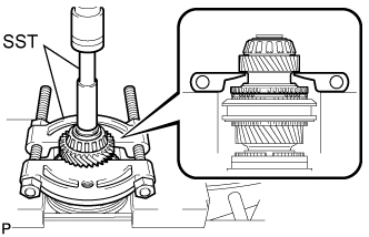
REMOVE OUTPUT SHAFT FRONT BEARING
-
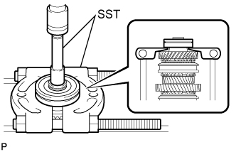
Using SST and a press, press out the output shaft front bearing from the No. 1 output shaft.
- SST
- 09201-31010
- 09950-00020
-
-
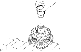
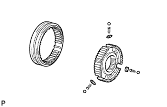
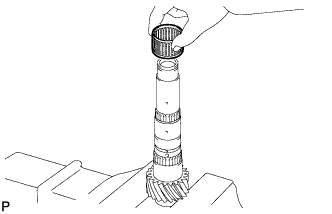
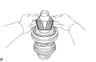
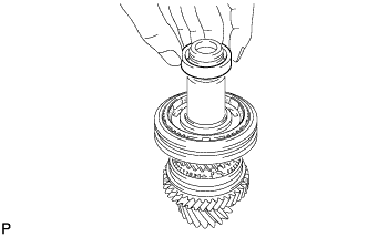
REMOVE 3RD DRIVEN GEAR
-
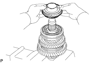
Remove the 3rd driven gear from the No. 1 output shaft.
-
-
REMOVE SPACER
-
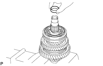
Remove the spacer from the No. 1 output shaft.
-
-
REMOVE NEEDLE ROLLER BEARING
-
Remove the needle roller bearing from the No. 1 output shaft.
-
-
REMOVE 3RD DRIVEN GEAR SYNCHRONIZER RING SET
-
Remove the 3rd driven gear synchronizer ring set from the No. 1 output shaft.
-
-
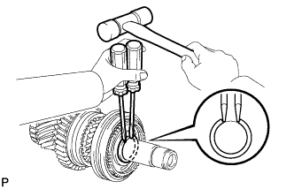
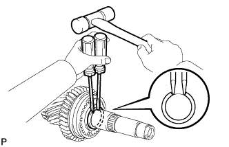
REMOVE SHAFT SNAP RING
-
Using 2 screwdrivers and a hammer, tap out the shaft snap ring from the No. 1 output shaft.
-
-
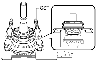
REMOVE 4TH DRIVEN GEAR
-
Using SST and a press, press out the No. 2 transmission hub sleeve, 4th driven gear synchronizer ring set and 4th driven gear from the No. 1 output shaft.
- SST
- 09950-00020
-
-
REMOVE 4TH DRIVEN GEAR SYNCHRONIZER RING SET
-
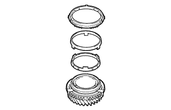
Remove the 4th driven gear synchronizer ring set from the 4th driven gear.
-
-
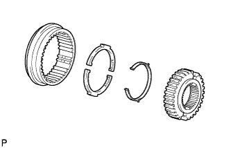
REMOVE NO. 2 TRANSMISSION CLUTCH HUB
-
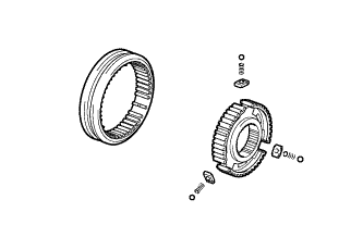
Remove the clutch hub, 3 keys, 3 balls and 3 key springs from the hub sleeve.
Note
Pay attention to prevent the balls and springs from scattering.
-
-
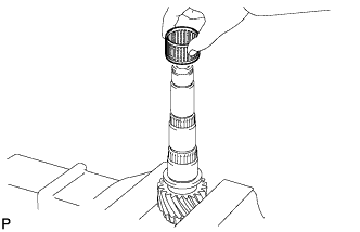
REMOVE NEEDLE ROLLER BEARING
-
Remove the 2 pieces of the needle roller bearing from the No. 1 output shaft.
-
-
REMOVE SPACER
-
Remove the spacer from the No. 1 output shaft.
-
-
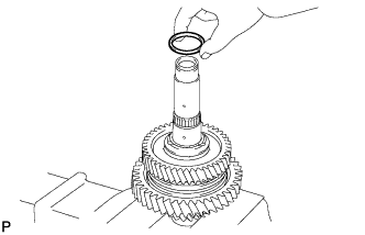
REMOVE OUTPUT SHAFT BEARING SHAFT SNAP RING
-
Using a snap ring expander, remove the output shaft bearing shaft snap ring from the No. 1 output shaft.
-
-
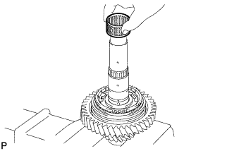
REMOVE INNER 2ND DRIVEN GEAR BEARING RACE
-
Remove the inner 2nd driven gear bearing race from the No. 1 output shaft.
-
-
REMOVE 2ND DRIVEN GEAR
-
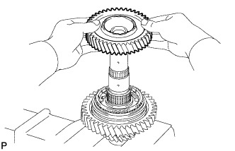
Remove the 2nd driven gear from the No. 1 output shaft.
-
-
REMOVE NEEDLE ROLLER BEARING
-
Remove the needle roller bearing from the No. 1 output shaft.
-
-
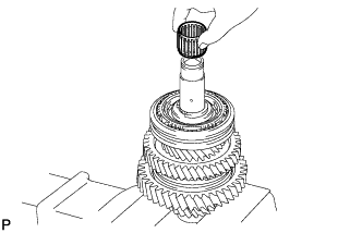
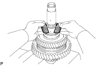
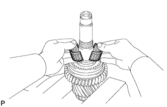
REMOVE SYNCHROMESH SHIFTING KEY BALL
-
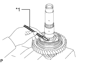
Text in Illustration *1 Magnet Hand Using a magnet hand, remove the synchromesh shifting key ball from the No. 1 output shaft.
-
-
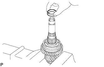
REMOVE 2ND DRIVEN GEAR SYNCHRONIZER RING SET
-
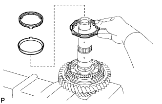
Remove the 2nd driven gear synchronizer ring set from the No. 1 output shaft.
-
-
REMOVE 1ST DRIVEN GEAR
-
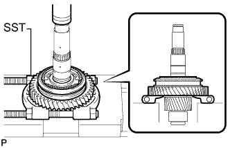
Using SST and a press, press out the No. 1 transmission hub sleeve, 1st driven gear synchronizer ring set and 1st driven gear from the No. 1 output shaft.
- SST
- 09950-00020
-
-
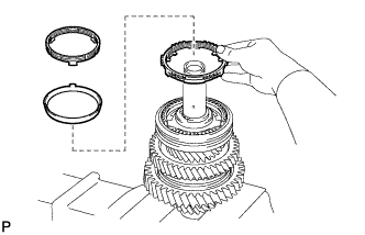
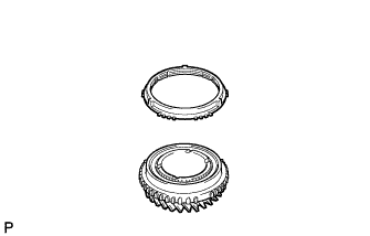
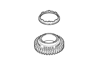
REMOVE 1ST DRIVEN GEAR SYNCHRONIZER RING SET
-
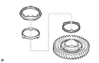
Remove the synchronizer ring set from the 1st driven gear.
-
-
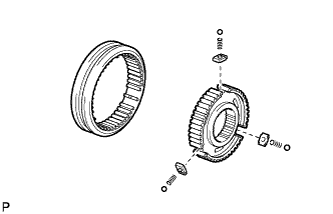
REMOVE NO. 1 TRANSMISSION CLUTCH HUB
-
Remove the clutch hub, 3 keys, 3 balls and 3 key springs from the hub sleeve.
Note
Pay attention to prevent the balls and springs from scattering.
-
-
REMOVE NEEDLE ROLLER BEARING
-
Remove the needle roller bearing from the No. 1 output shaft.
-
-
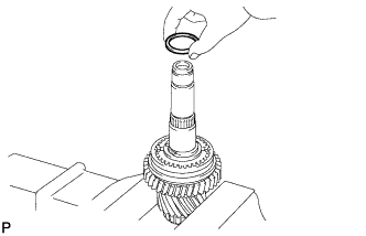
REMOVE OUTPUT SHAFT FRONT BEARING SHAFT SNAP RING
-
Using a snap ring expander, remove the output shaft front bearing shaft snap ring from the No. 1 output shaft.
-
-
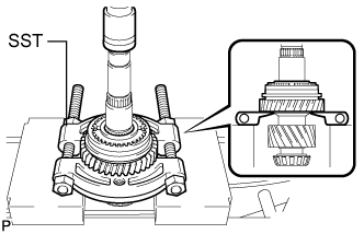
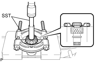
REMOVE OUTPUT SHAFT FRONT BEARING
-
Using SST and a press, press out the output shaft front bearing from the No. 1 output shaft.
- SST
- 09201-31010
- 09950-00020
-
-
INSPECT 5TH DRIVEN GEAR THRUST CLEARANCE
-

Using a feeler gauge, measure the 5th driven gear thrust clearance.
Standard clearance 0.10 to 0.55 mm (0.00394 to 0.0216 in.) Maximum clearance 0.55 mm (0.0216 in.) If the clearance is more than the maximum, replace the 5th driven gear, needle roller bearing or output shaft. Replace the part or parts determined to be the most likely cause of the problem.
-
-
INSPECT 5TH DRIVEN GEAR RADIAL CLEARANCE
-
Using a dial indicator, measure the 5th driven gear radial clearance.
Standard clearance 0.015 to 0.066 mm (0.000591 to 0.00259 in.) Maximum clearance 0.066 mm (0.00259 in.) If the clearance is more than the maximum, replace the 5th driven gear, needle roller bearing or output shaft. Replace the part or parts determined to be the most likely cause of the problem.
-
-
INSPECT 6TH DRIVEN GEAR THRUST CLEARANCE
-
Using a feeler gauge, measure the 6th driven gear thrust clearance.
Standard clearance 0.10 to 0.55 mm (0.00394 to 0.0216 in.) Maximum clearance 0.55 mm (0.0216 in.) If the clearance is more than the maximum, replace the 6th driven gear, needle roller bearing or output shaft. Replace the part or parts determined to be the most likely cause of the problem.
-
-
INSPECT 6TH DRIVEN GEAR RADIAL CLEARANCE
-
Using a dial indicator, measure the 6th driven gear radial clearance.
Standard clearance 0.015 to 0.066 mm (0.000591 to 0.00259 in.) Maximum clearance 0.066 mm (0.00259 in.) If the clearance is more than the maximum, replace the 6th driven gear, needle roller bearing or output shaft. Replace the part or parts determined to be the most likely cause of the problem.
-
-
INSPECT REVERSE DRIVEN GEAR THRUST CLEARANCE
-
Using a feeler gauge, measure the reverse driven gear thrust clearance.
Standard clearance 0.11 to 0.34 mm (0.00434 to 0.0133 in.) Maximum clearance 0.34 mm (0.0133 in.) If the clearance is more than the maximum, replace the reverse driven gear, needle roller bearing or output shaft. Replace the part or parts determined to be the most likely cause of the problem.
-
-
INSPECT REVERSE DRIVEN GEAR RADIAL CLEARANCE
-
Using a dial indicator, measure the reverse driven gear radial clearance.
Standard clearance 0.015 to 0.068 mm (0.000591 to 0.00267 in.) Maximum clearance 0.068 mm (0.00267 in.) If the clearance is more than the maximum, replace the reverse driven gear, needle roller bearing or output shaft. Replace the part or parts determined to be the most likely cause of the problem.
-
-
REMOVE NO. 2 OUTPUT SHAFT BEARING SNAP RING
-
Using a snap ring expander, remove the No. 2 output shaft bearing snap ring from the No. 2 output shaft.
-
-
REMOVE NO. 2 OUTPUT SHAFT REAR BEARING
-
Using SST and a press, press out the rear bearing and 6th driven gear from the No. 2 output shaft.
- SST
- 09201-31010
- 09950-00020
-
-
REMOVE NEEDLE ROLLER BEARING
-
Remove the 2 pieces of the needle roller bearing from the No. 2 output shaft.
-
-
REMOVE SPACER
-
Remove the spacer from the No. 2 output shaft.
-
-
REMOVE 6TH GEAR SYNCHRONIZER RING
-
Remove the 6th gear synchronizer ring from the No. 2 output shaft.
-
-
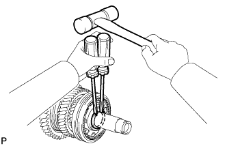
REMOVE SHAFT SNAP RING
-
Using 2 screwdrivers and a hammer, tap out the shaft snap ring from the No. 2 output shaft.
-
-
REMOVE 5TH DRIVEN GEAR
-
Using SST and a press, press out the No. 3 transmission hub sleeve, 5th driven gear synchronizer ring and 5th driven gear from the No. 2 output shaft.
- SST
- 09950-00020
-
-
REMOVE 5TH DRIVEN GEAR SYNCHRONIZER RING
-
Remove the 5th driven gear synchronizer ring from the 5th driven gear.
-
-
REMOVE NO. 3 TRANSMISSION CLUTCH HUB
-
Remove the No. 3 transmission clutch hub, 3 keys, 3 balls and 3 key springs from the hub sleeve.
Note
Pay attention to prevent the balls and springs from scattering.
-
-
REMOVE OUTPUT SHAFT COLLAR
-
Remove the output shaft collar from the No. 2 output shaft.
-
-
REMOVE 5TH GEAR NEEDLE ROLLER BEARING
-
Remove the 2 pieces of the 5th gear needle roller bearing from the No. 2 output shaft.
-
-
REMOVE 5TH GEAR BEARING SPACER
-
Remove the 5th gear bearing spacer from the No. 2 output shaft.
-
-
REMOVE SHAFT SNAP RING
-
Using 2 screwdrivers and a hammer, remove the shaft snap ring from the No. 2 output shaft.
-
-
REMOVE REVERSE DRIVEN GEAR
-
Using SST and a press, press out the No. 4 transmission hub sleeve, reverse driven gear synchronizer ring set and reverse driven gear from the No. 2 output shaft.
- SST
- 09950-00020
-
-
REMOVE REVERSE DRIVEN GEAR SYNCHRONIZER RING
-
Remove the reverse driven gear synchronizer ring from the reverse gear.
-
-
REMOVE NO. 4 TRANSMISSION CLUTCH HUB
-
Remove the No. 4 transmission clutch hub, synchromesh shifting key spring and 2 synchromesh shifting keys from the transmission hub sleeve.
-
-
REMOVE NEEDLE ROLLER BEARING
-
Remove the needle roller bearing from the No. 2 output shaft.
-
-
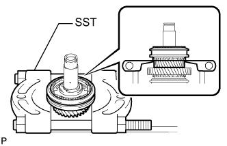
REMOVE NO. 2 OUTPUT SHAFT FRONT BEARING
-
Using SST and a press, press out the No. 2 output shaft front bearing from the No. 2 output shaft.
- SST
- 09201-31010
- 09950-00020
-